Objective:
Learn how to use Reaction Force Response in Topology Optimization.
Procedure:
The Reaction Force Response block creates a design response that measures the sum of reaction force vectors across a boundary. The response is derived from the solution of a linear static structural analysis.
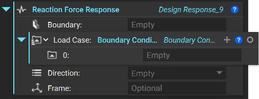
The inputs of the block are
- Boundary: The FE boundary on which the design response will be computed.
- Load Case: Load case for the design response.
- Direction: Operation will be applied after summing all reaction force vectors over the Boundary input. |X| will compute the magnitude of the reaction force vector projected onto the X-axis, |XY| will compute the magnitude of the reaction force vector projected onto the plane spanned by the X-axis and Y-axis, and |XYZ| will compute the magnitude of the non-projected reaction force vector.
- Frame: Reference frame that the reaction force will be computed in. If a frame is not specified, the global coordinate system will be used.
- Output: Design Response
Tips
- The Reaction Force Response block works best when supplemented with Structural Compliance, Stress, or Displacement Response blocks.
- When the number of regions to be constrained is small, they can be included as individual design response constraints in the optimization problem.
- If the number of regions is large (10-100), it should be used with the new Combine Design Responses block. The implementation has been optimized to solve only one adjoint problem rather than 100 individual adjoint problems, greatly improving compute time. We recommend using List processing for such workflows.
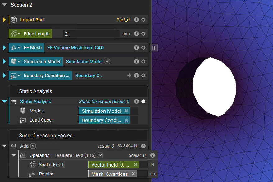
How do you calculate the Reaction Force?
You can use a combination of a Evaluate Field block and the results from Static Analysis to calculate the reaction forces. (How to use reaction forces in a secondary analysis). You can then use an Add block to sum all the reaction forces.
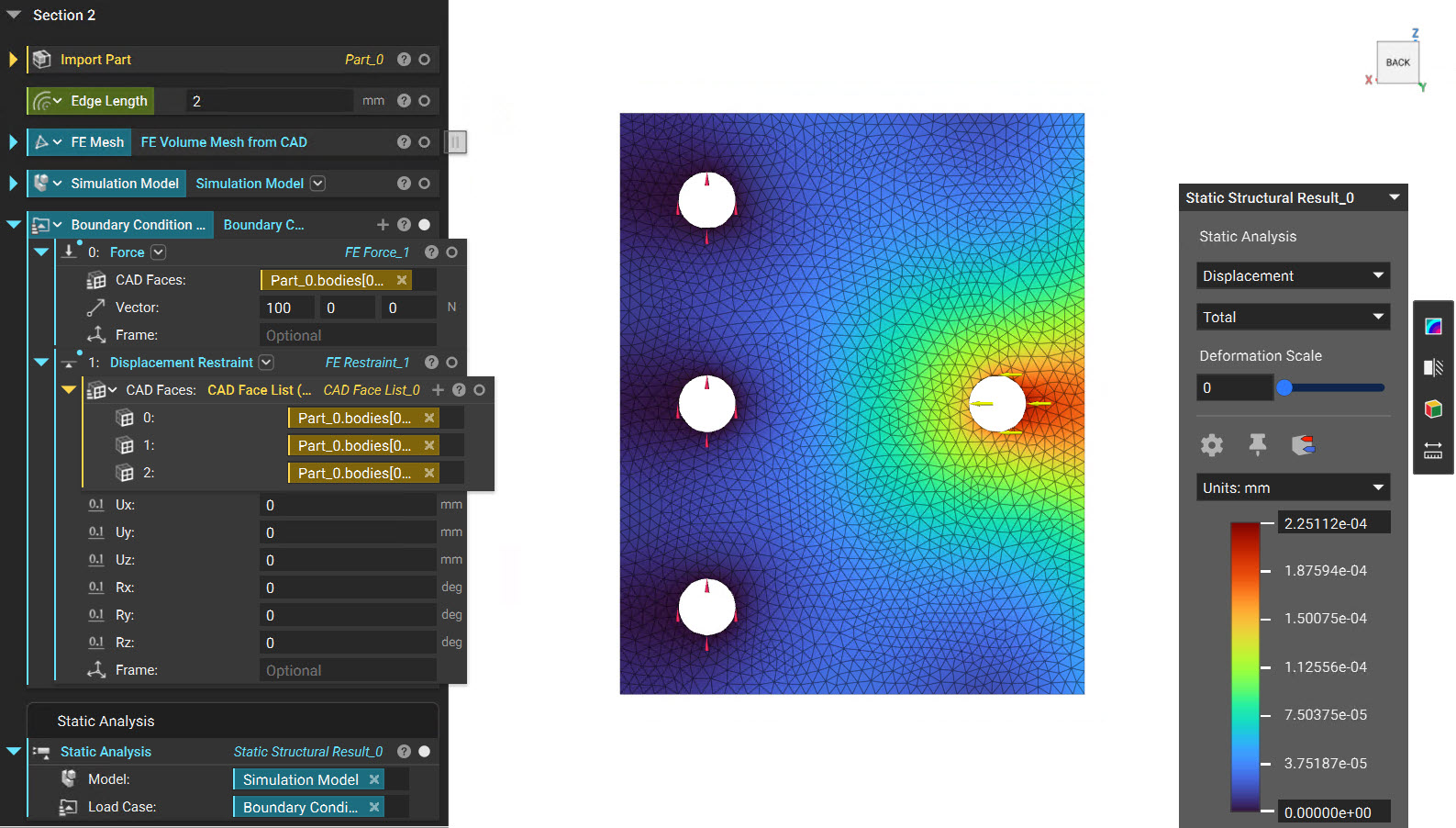
Example
We have a plate restrained in the 3 holes on the left, and a Force of [100,0,0] is applied on the right side hole.
Topology Optimization Setup 1 (No Reaction Force)
We will now use Topology Optimization with the following objectives and constraints:
| Objective | Constraint |
|---|---|
| Structural Compliance Response [MINIMIZE] |
Volume Fraction Constraint [0.15] Passive Region Constraint [Restrained Holes] |
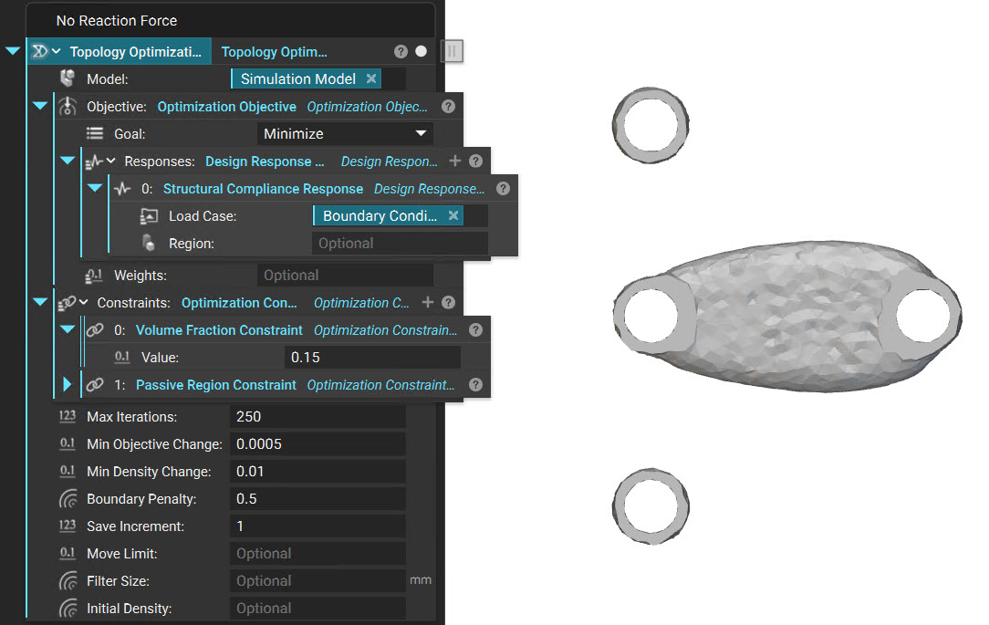
We notice that the Passive Regions we selected are disconnected. This result is not useful since we need a result with no disconnecting regions.
Topology Optimization Setup 2 (Reaction Force - Sum)
| Objective | Constraint |
|---|---|
| Structural Compliance Response [MINIMIZE] |
Volume Fraction Constraint [0.15] Passive Region Constraint [Restrained Holes] Reaction Force Response [Sum] |
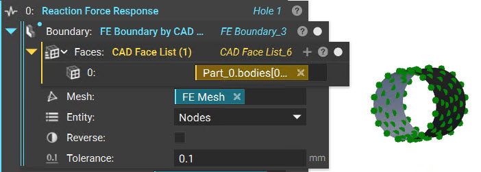
We use the Reaction Force Response block with each face individually, use the Boundary Condition we created earlier, and set the Direction to |XYZ|.
Let's repeat the same step to select the other two restrained holes as well.
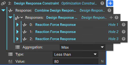
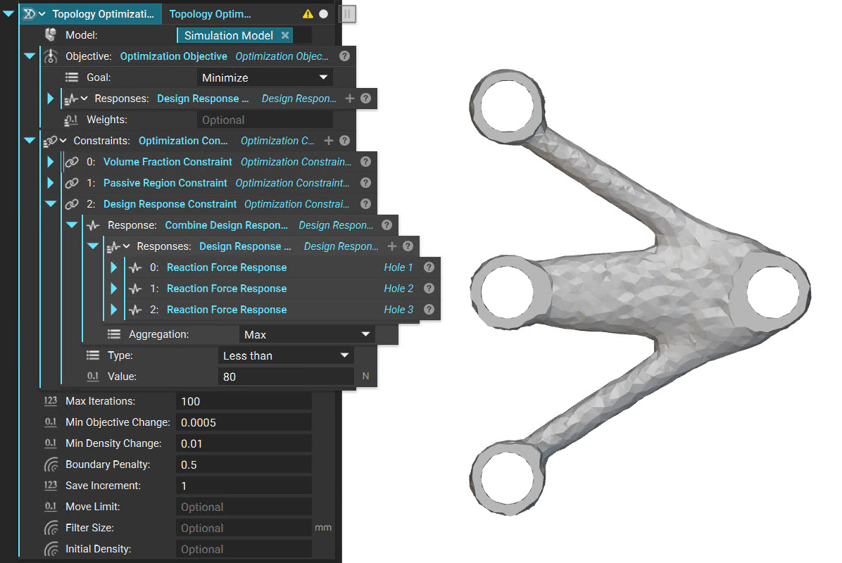
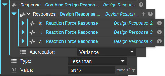
We will now use the Combine Design Response block to combine the list of design responses into a single response. Since we need to ensure that the Maximum Reaction Force is less than a certain value, we will use the Aggregation as Max in this instance.
Place this response as an input to the Design Response Constraint and select the Type as Less than with a Value of 80 N.
When we look at the results now, we see that there are no disconnecting regions. We can use the result here to check if the Reaction Forces are maintained below 80N.
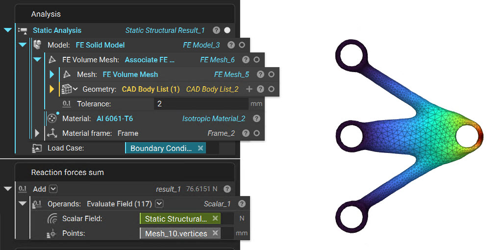
We can use the Associate FE Mesh (How to use a CAD Face in a boundary condition) block to use the CAD Faces for boundary conditions. Running the static analysis shows that the Sum of Reaction Forces is less than 80N, which we had specified in the Topology optimization block.
Topology Optimization Setup 2 (Reaction Force - Variance)
| Objective | Constraint |
|---|---|
| Structural Compliance Response [MINIMIZE] |
Volume Fraction Constraint [0.15] Passive Region Constraint [Restrained Holes] Reaction Force Response [Variance] |
When we set the Aggregation to Variance and enter a Value of 5N^2 with a Type Less, then it ensures that the variance between the Reaction Forces of each hole is less than 5 N^2.
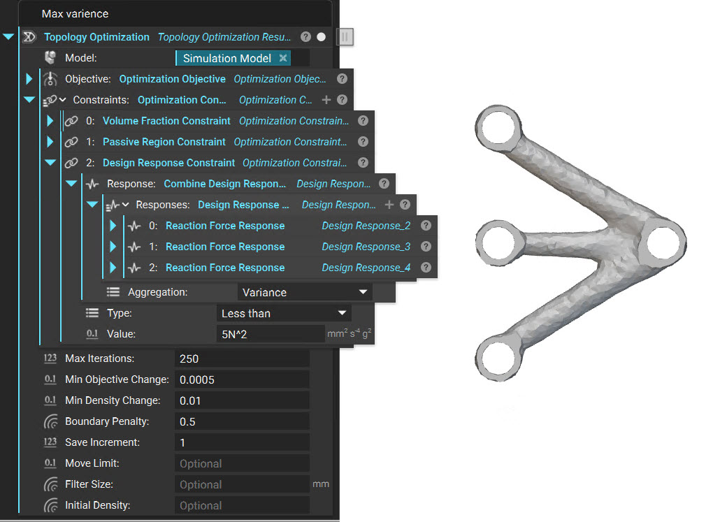
We can see that the distribution is much more uniform here compared to the earlier setup.
And that's it. You have successfully learned how to use Reaction Force Response in Topology Optimization. If you still have any questions, contact support@ntop.com.