Summary:
This article demonstrates the three new methods of rib mapping. Each method has pros and cons based on the intended design and starting geometry, so we recommend reviewing all possible methods. The last section shows how to combine rib mapping with field-driven design. Each method has an example file at the end of the section.
Common use-cases:
We define ribs as a pattern of 3D thin-walled structures that add support and rigidity to parts. Ribs are often applied to thin-walled components such as housings, panels, manifolds, piping, and more.
Glossary:
- Lattice: A lattice is a 3D structure with thickness made from a pattern of material and air.
- Graph: A line-based pattern representing rib centerlines. In nTop, graphs store connectivity information between a network of line segments and are also used for lattices.
- Rib: Ribs are a pattern of 3D thin-walled shapes of a specified thickness in a specified direction on the contour of an existing part.
Methods:
Graph Projection Mapping
|
 |
Graph Projection mapping is a method of creating ribbing patterns that approximate a target shape using a simple guide shape. For the initial release, these guide shapes are Planes, Cylinders, and Tubes (Swept cylinders). This technique should be used when mapping across many CAD faces or small surface details and when the target shape resembles one of the guide shapes. Multiple projection mapping steps can be performed if there are multiple regions of a part. Additionally, it should be used when periodic patterns are desired.
Graph by Planar Projection
1. Start by creating an implicit body. This body will act as the target for projection mapping; the rib pattern will be projected to this body. In this case, it’s a CAD face converted to an implicit body, but CAD geometry is unnecessary for this workflow.
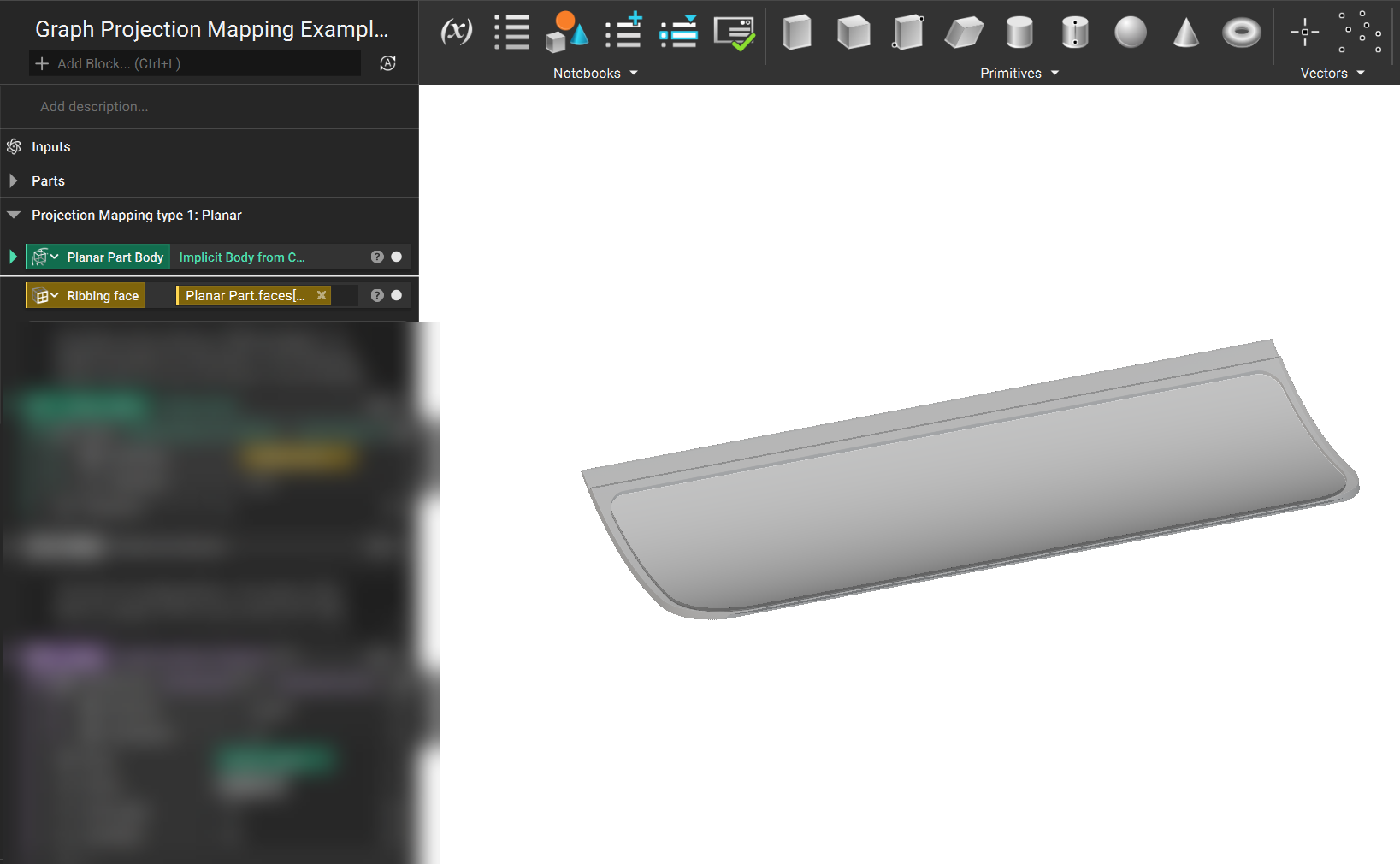
2. Due to the shape of this part, Planar mapping results in a pattern with minimal distortion. Create a plane positioned with its normal facing the part and select a unit cell using the 2D Unit Cell (BETA) block. Use the Graph by Planar Projection (BETA) block to project the pattern to the surface with the desired rib centerline spacing. This block will project from the plane to the first intersection point along the plane’s normal direction. The Tolerance input controls how beams are subdivided to capture surface detail and boundaries.
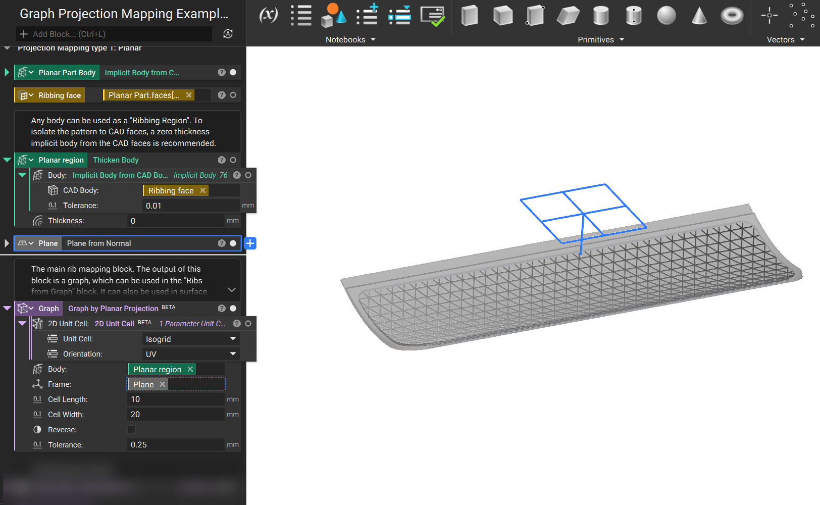
3. Due to the direction we will be extruding the ribs, we want to prevent gaps from appearing between the ribs and the side walls of the part. To accomplish this, we can use the Extend Open Lattice Beams block to modify the graph. Once done, extract the Lattice -> Thick Graph -> Graph property and use this as the graph for the remaining steps.
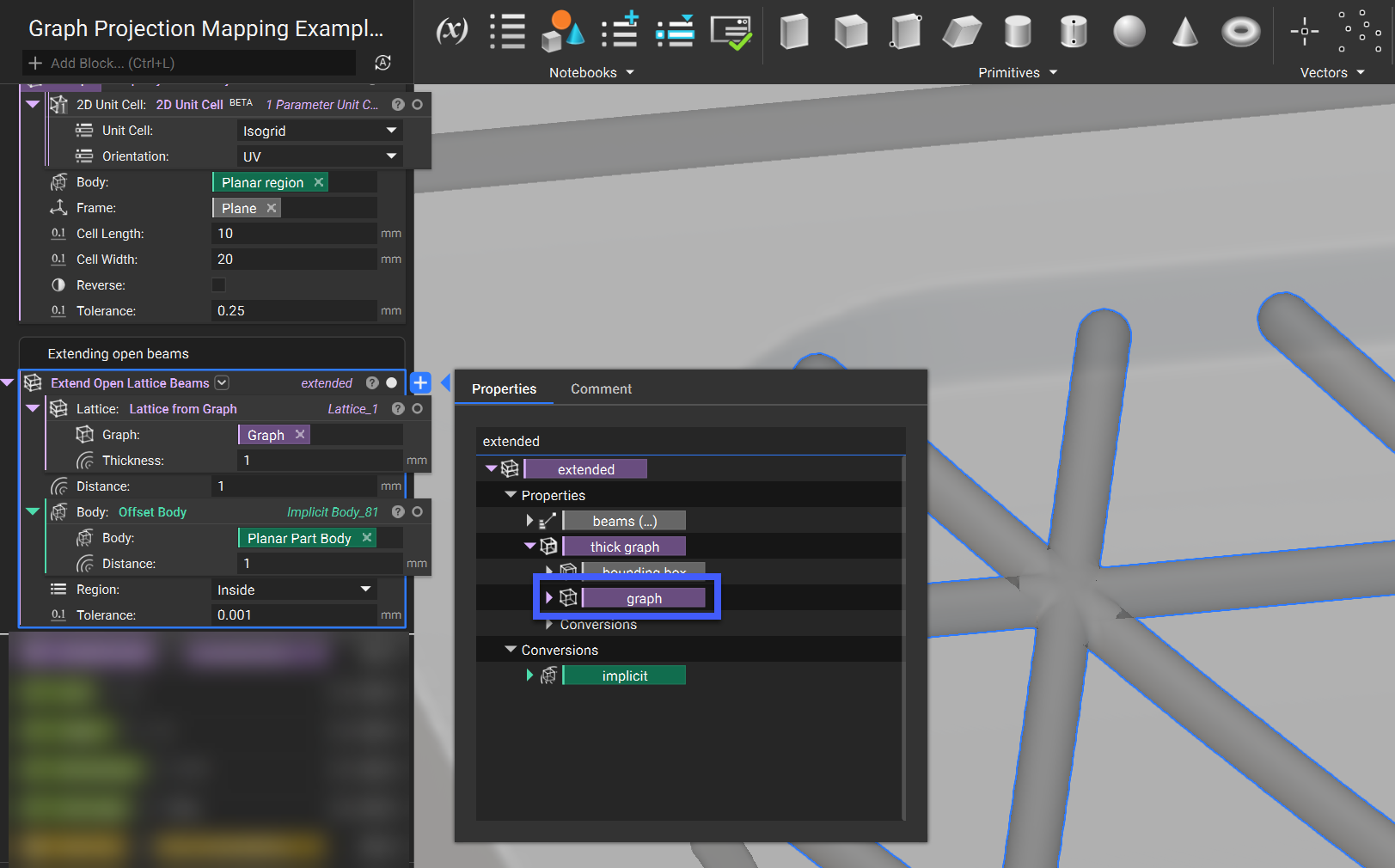
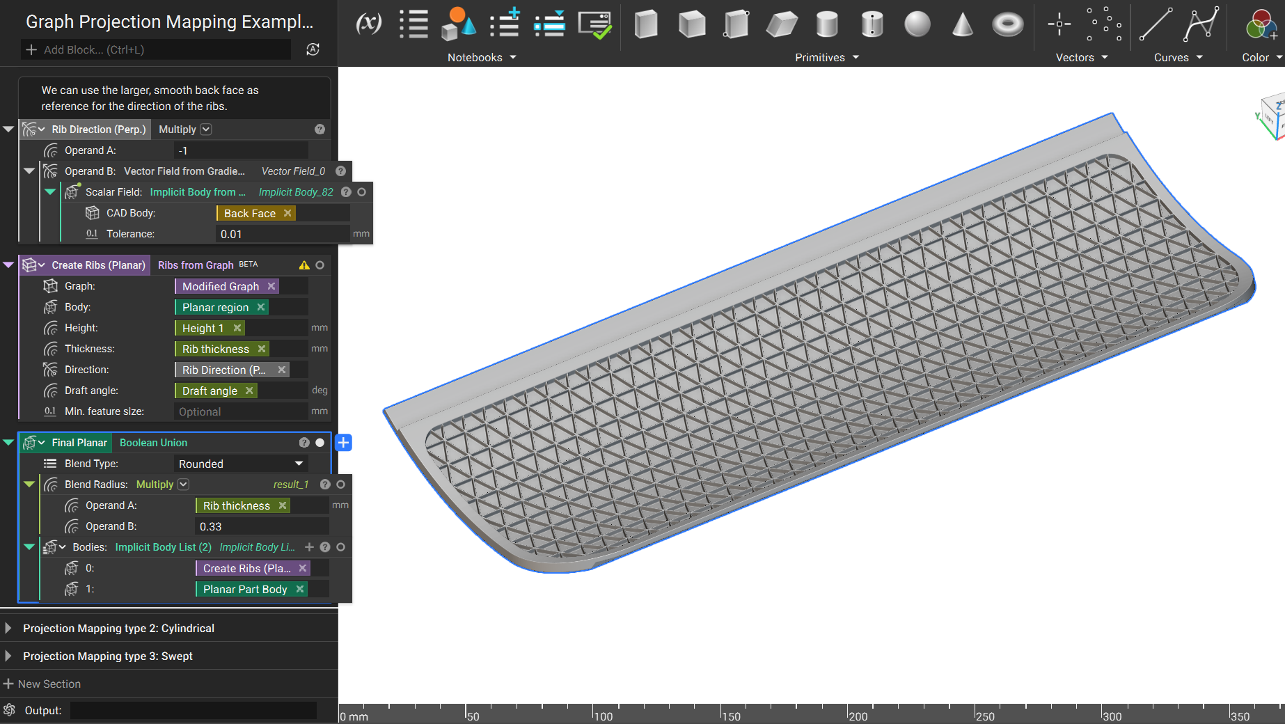
4. Use this graph in the Ribs from Graph (BETA) block to create solid ribs. To define a custom direction of extrusion (instead of just using the normal of the target, which is often acceptable), we will use another CAD face (“Back Face” in this example). This is because it is larger and smoother and will have consistent normals around the boundary of the projected Graph. Create a vector field from its gradient, which will become the extrusion direction. At this point, we can also specify the ribs' Thickness, Height, and Draft angle.
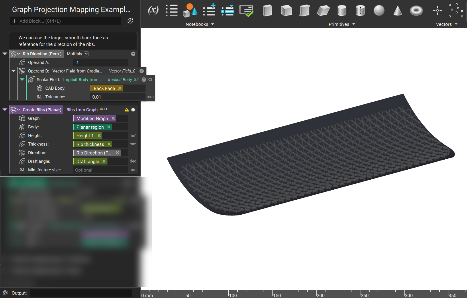
5. Perform a Boolean Union to join the ribs to the base part geometry (in this case, converted from a CAD body to an Implicit Body). At this stage, a Blend Radius at the base of the ribs can be applied.
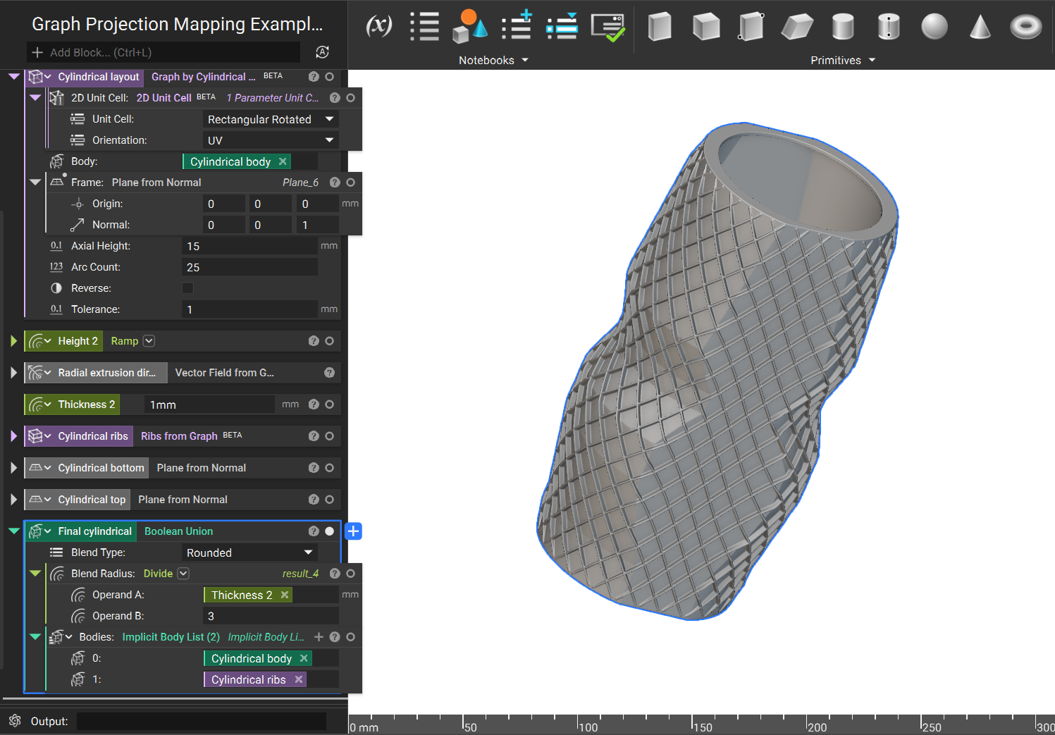
Graph by Cylindrical Projection
1. In this example, the projection target is an implicit body with no CAD conversions created entirely in nTop. Start by defining a Frame using the Plane from Normal block. This will position an axis (corresponding with the Z axis of the Frame/Plane) to define cylindrical projection.
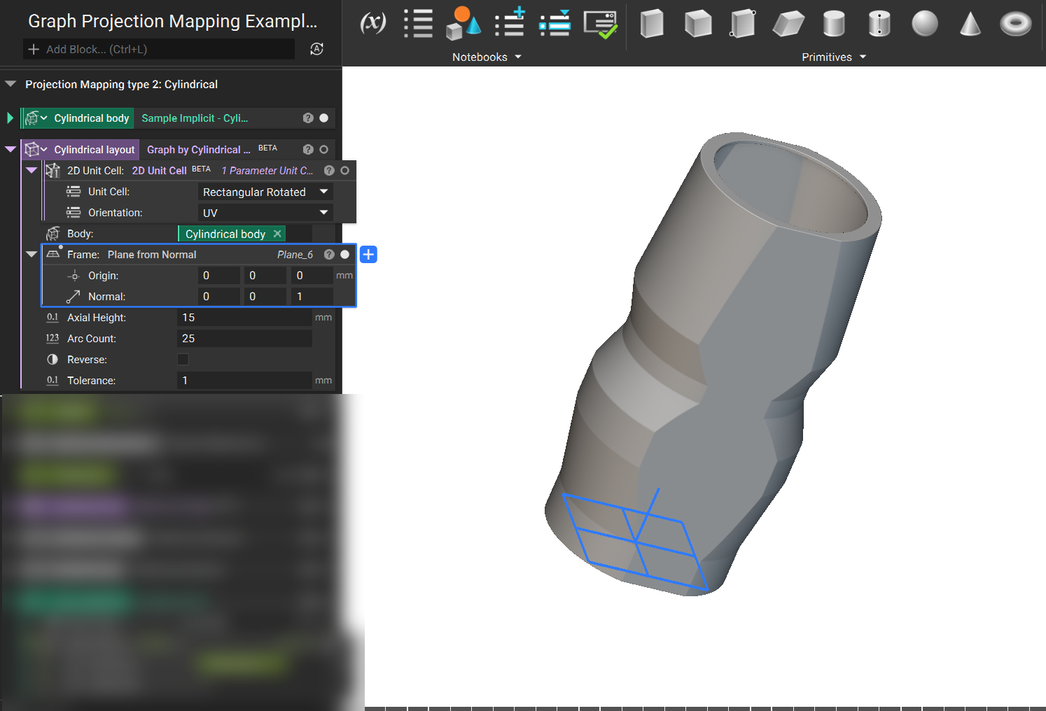
2. The Graph by Cylindrical Projection (BETA) block will project the pattern from infinitely far away toward the central axis and stop at the first point of intersection. If the pattern needs to be on the inside of the part, toggle the “reverse” input, and the pattern will be projected away from the axis.
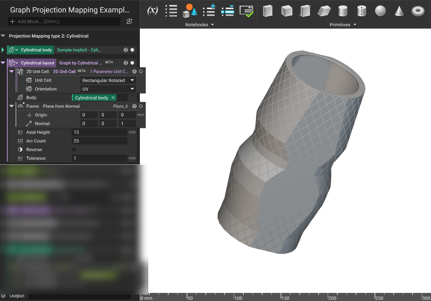
3. To create the solid ribs, follow the same steps as the Planar example. In this case, a height ramp was created to decrease the height of the ribs from the ends of the body.
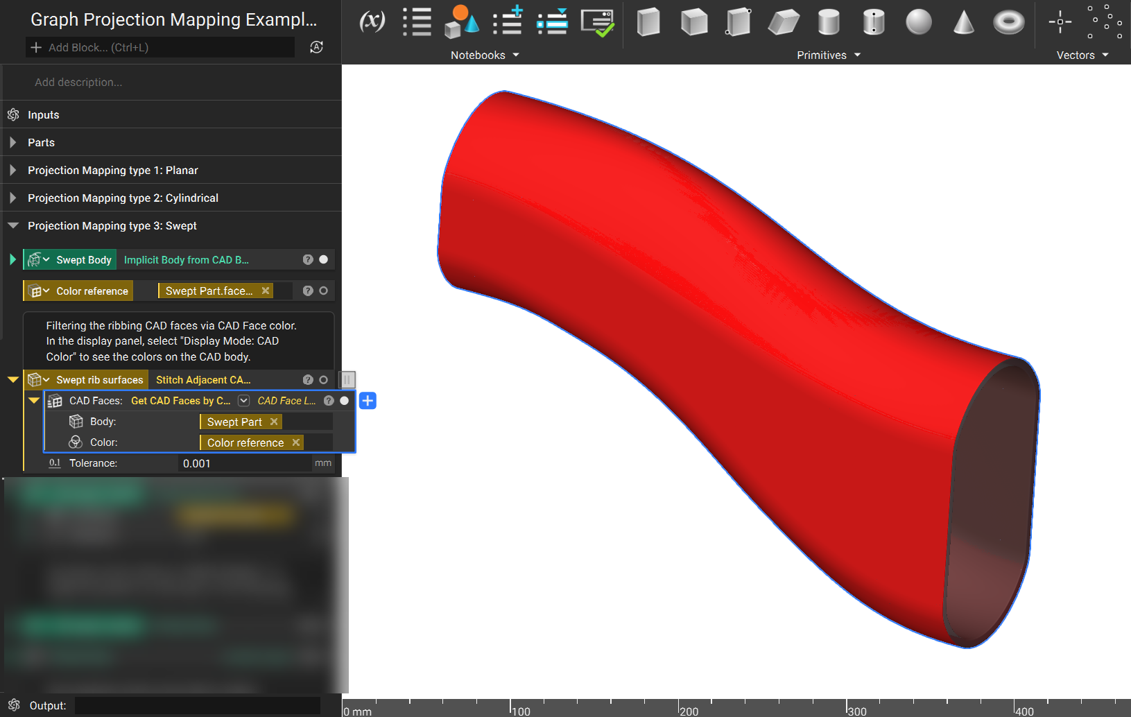
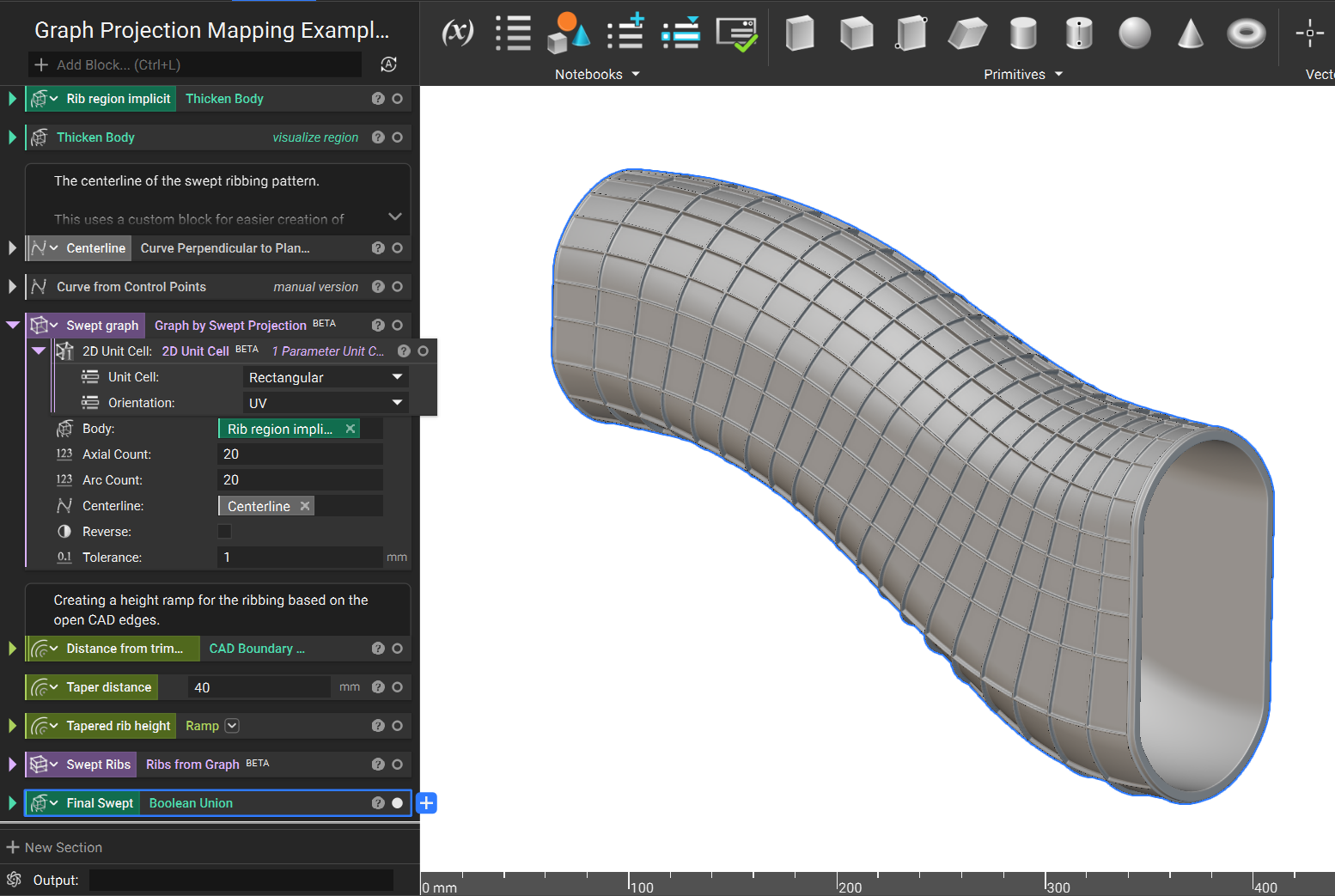
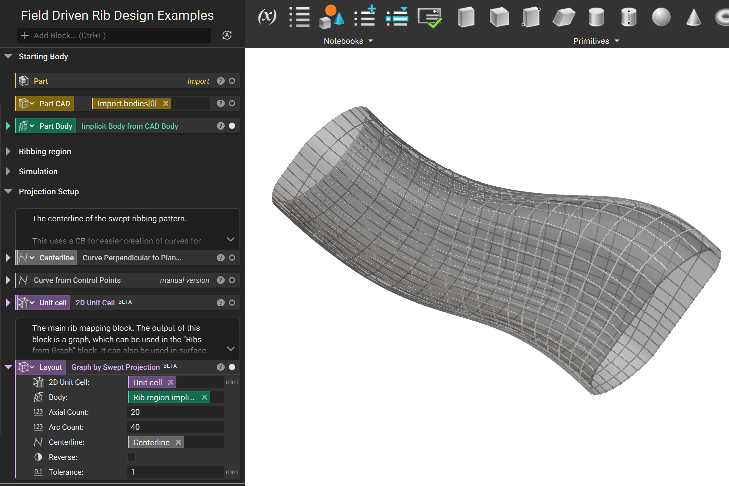
Graph by Swept Projection
Swept Projection is similar to Cylinder mapping. However, instead of a central axis, a centerline defines the projection mapping.
1. Like the Planar example, the projection target is defined by converting CAD faces into an implicit body. In this case, the Get Cad Faces by Color block was filtered down to the red faces.
2. Define a centerline for projection mapping. This single curve centerline can either be imported or created directly in nTop. In this example, it was made in nTop.
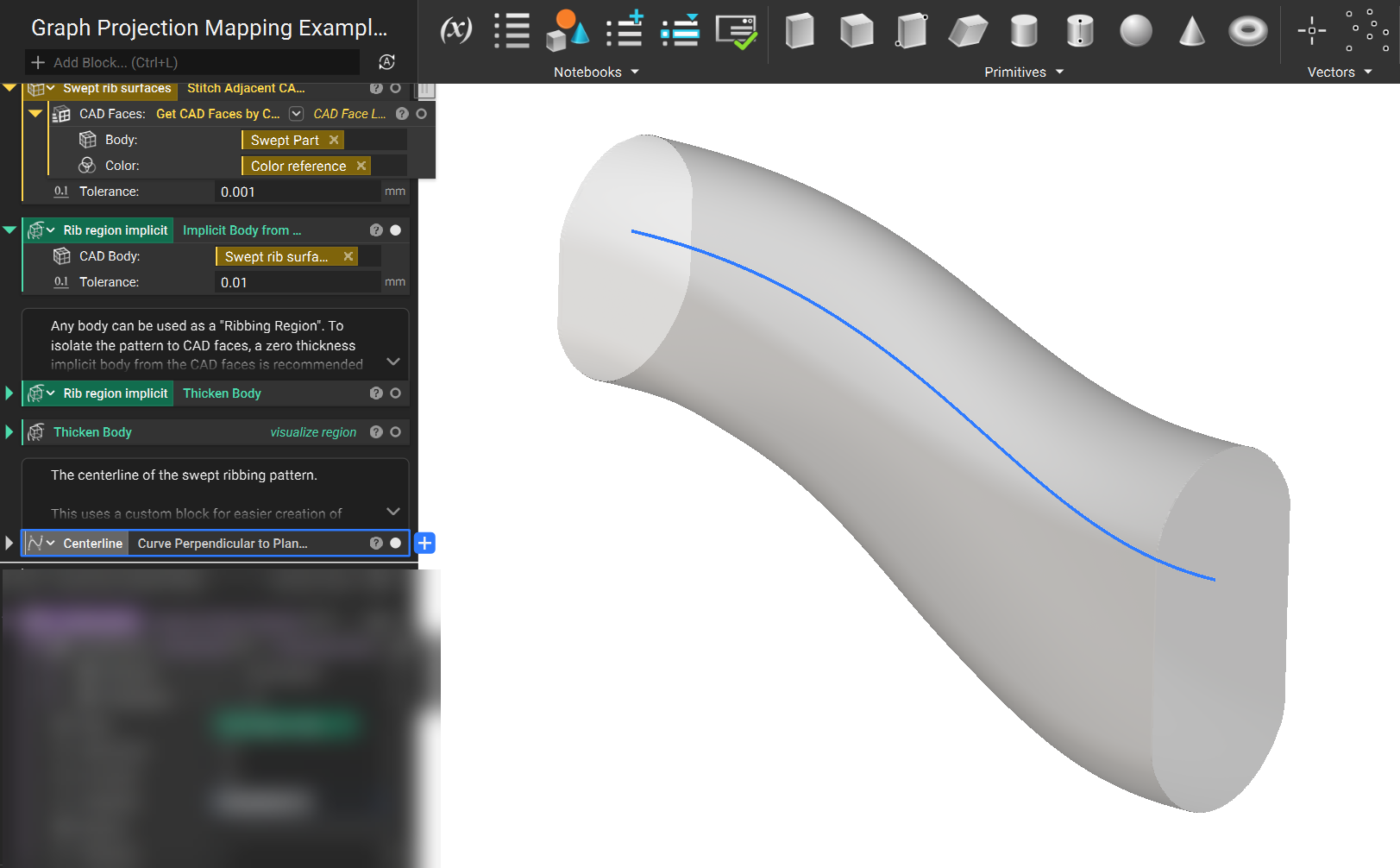
3. Use the Graph by Swept Projection (BETA) block to project the pattern to the target. The projection logic is otherwise the same as Graph by Cylindrical Projection (BETA) block.
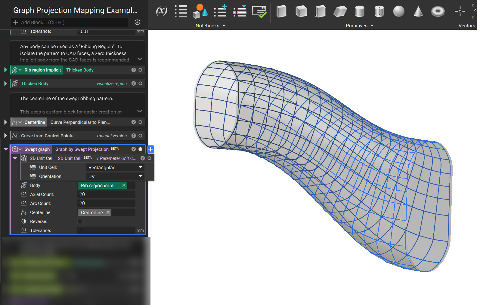
4. From here, the steps for creating solid ribs are the same as previous methods.
Example File:
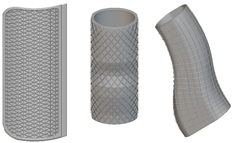
Conformal Graph Mapping
|
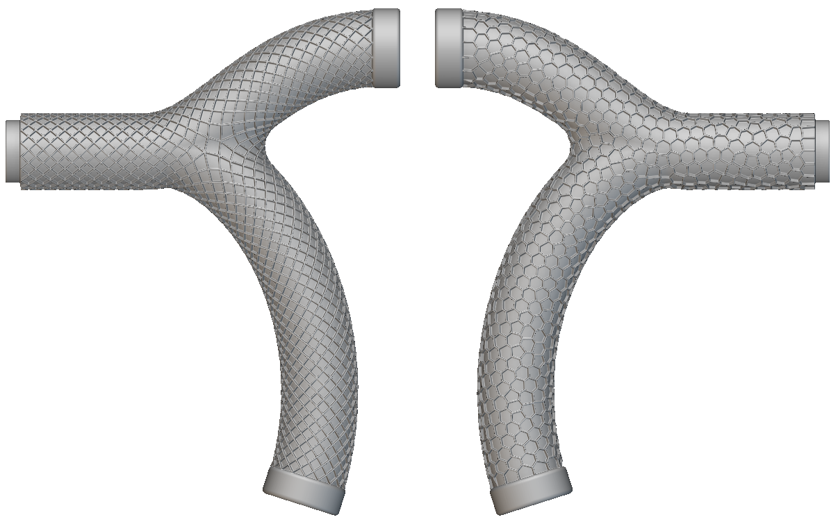 |
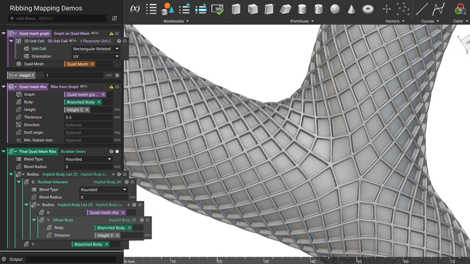
Projection mapping works for many types of parts, but not every part. Parts with complex curvature or branching geometry benefit from a more adaptive, organic approach. The tradeoff with this is that it is not always possible to align unit cells, so using a unit cell with rotational symmetry (such as “Rectangular”) is suggested. To accomplish this, a Quad Mesh is created on the part, and then a Graph is generated on the mesh.
Quad Mesh
1. Create a mesh of the region where the ribs should be located. In this case, a mesh generated from CAD faces was used, but an alternate approach would be to mesh the whole part and use Filter Mesh by Flood Fill block if no CAD faces are available.
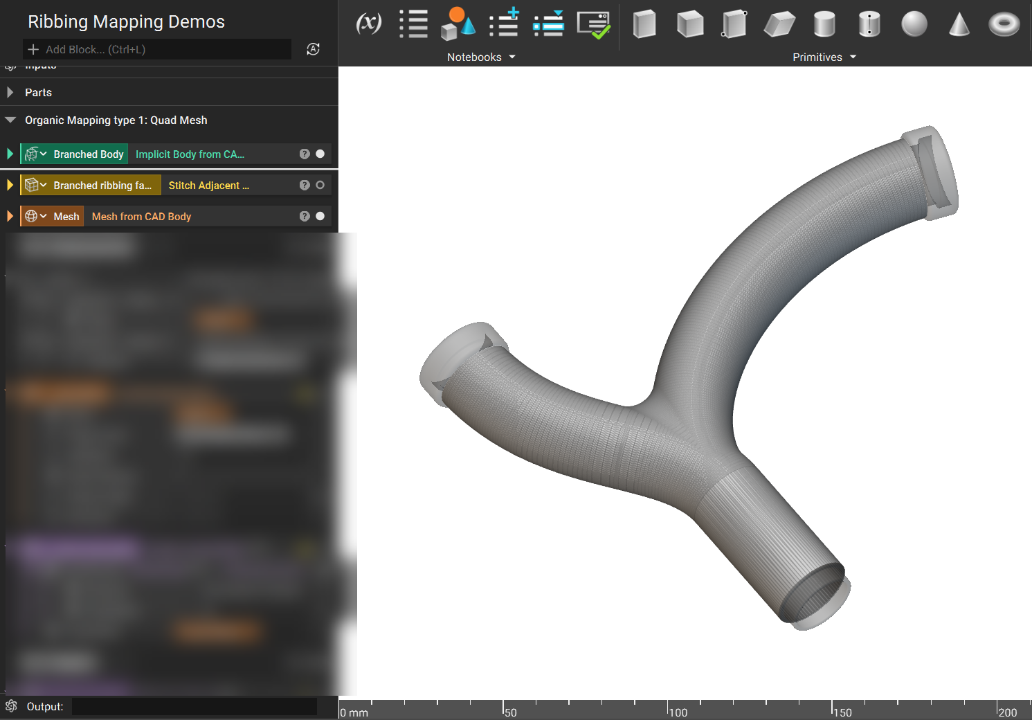
2. Use the Quadrangulate Mesh block to generate a quad mesh.
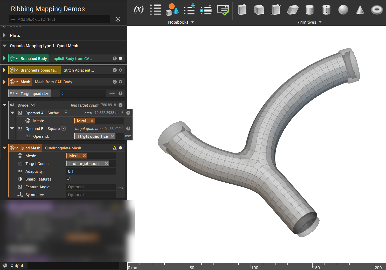
3. Select a 2D unit cell and use Graph on Quad Mesh (BETA) block to create the rib pattern.
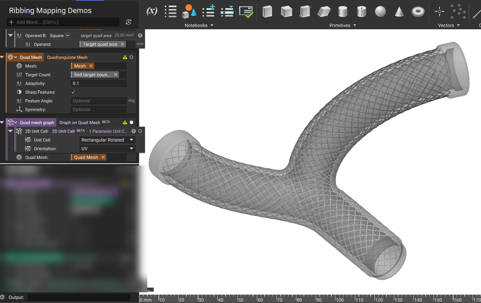
4. Finalize the ribs using Ribs from Graph (BETA) and implicit boolean blocks. Even though the graph on the quad mesh may deviate from the implicit body, the Ribs from Graph (BETA) block will conform the centerlines to the part.
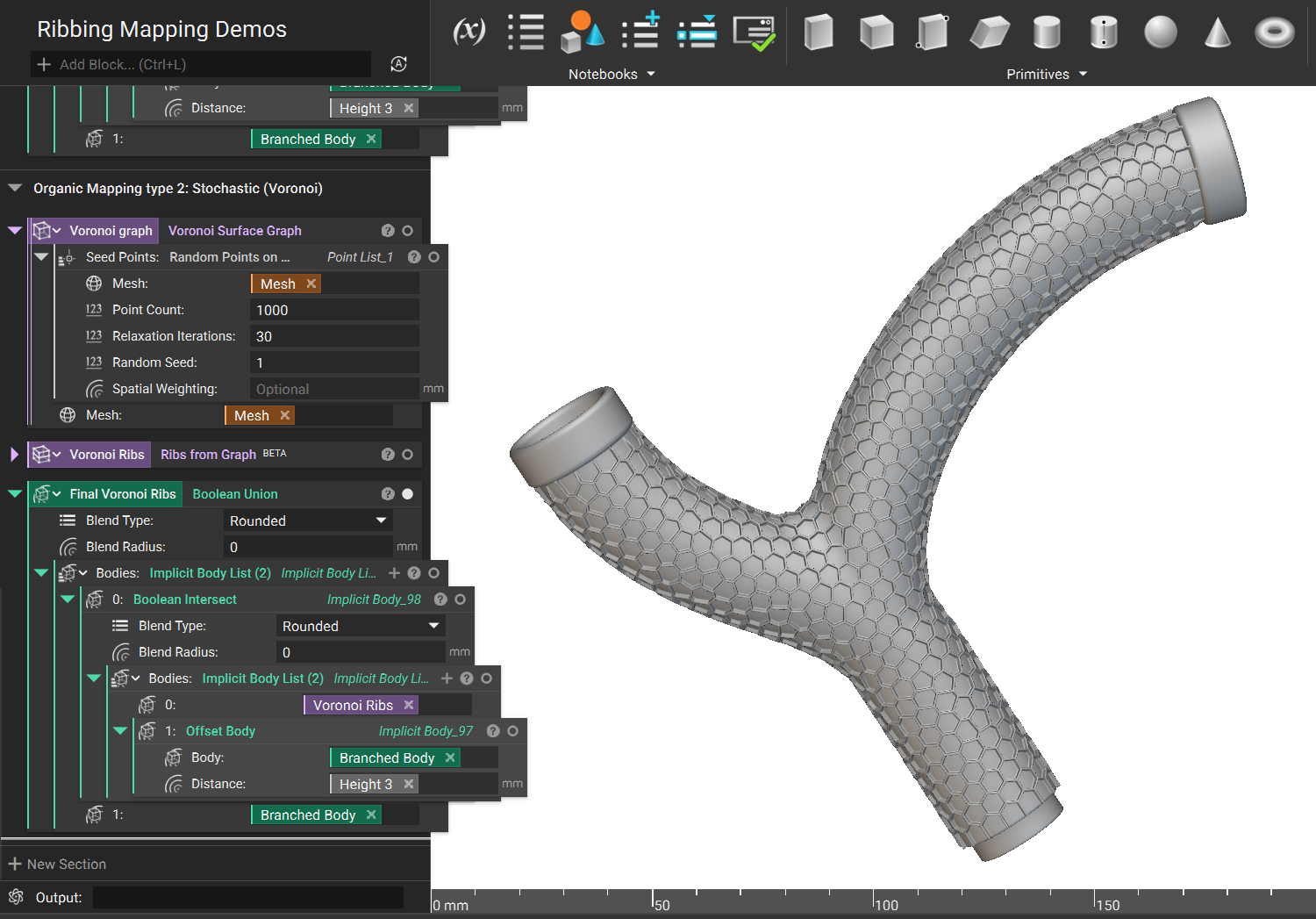
Voronoi Surface Graph
An alternative to Quad Mesh mapping is the Voronoi Surface Graph block. This approach allows field-driven spacing, though the layout will be stochastic, not periodic.
Example File:
CAD Face Mapping
|
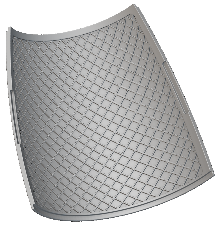 |
In some circumstances, the layout of the ribs can be fully defined by a single CAD face. In this scenario, use the Graph on CAD Face (BETA) block to generate the rib pattern.
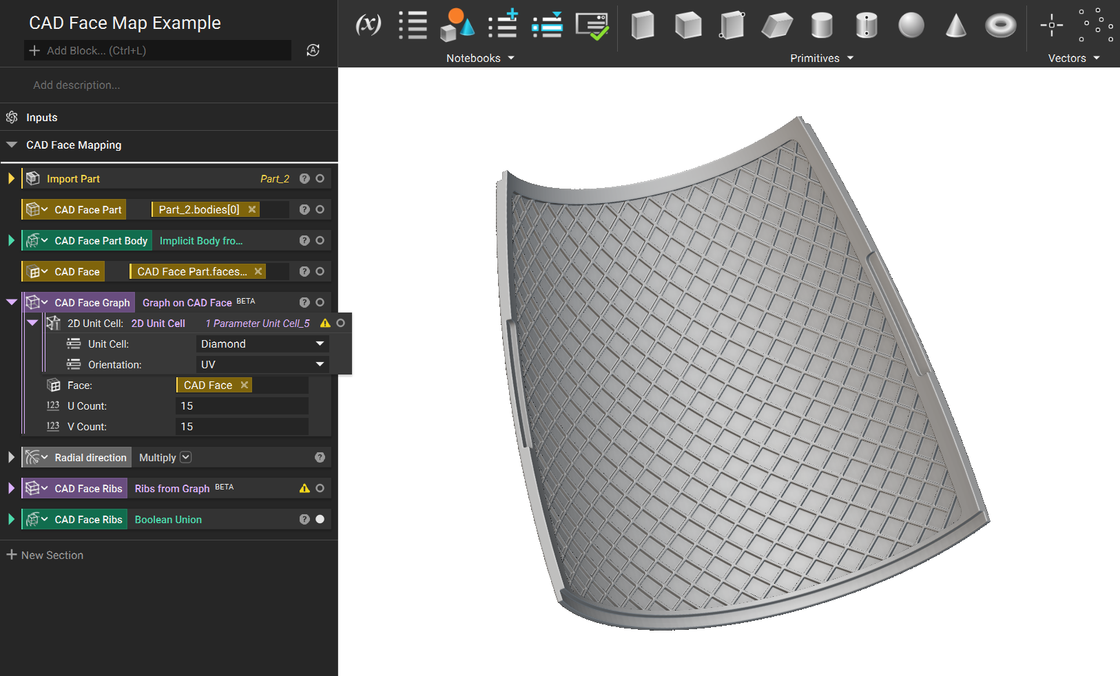
Example File:
Field Driven Rib Geometry
|
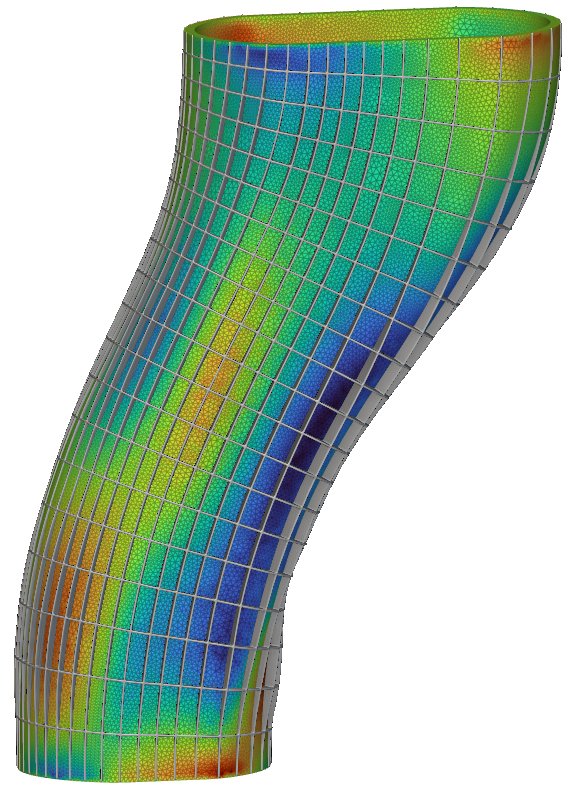 |
This section will demonstrate how to use simulation data to specify the height of ribs.
Simulation Driven Ribs
1. In this example, a rib pattern is projected following the same steps as in the previous section, "Graph by Swept Projection."
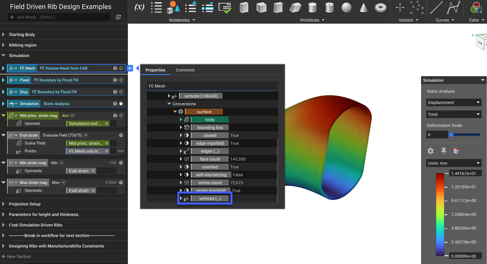
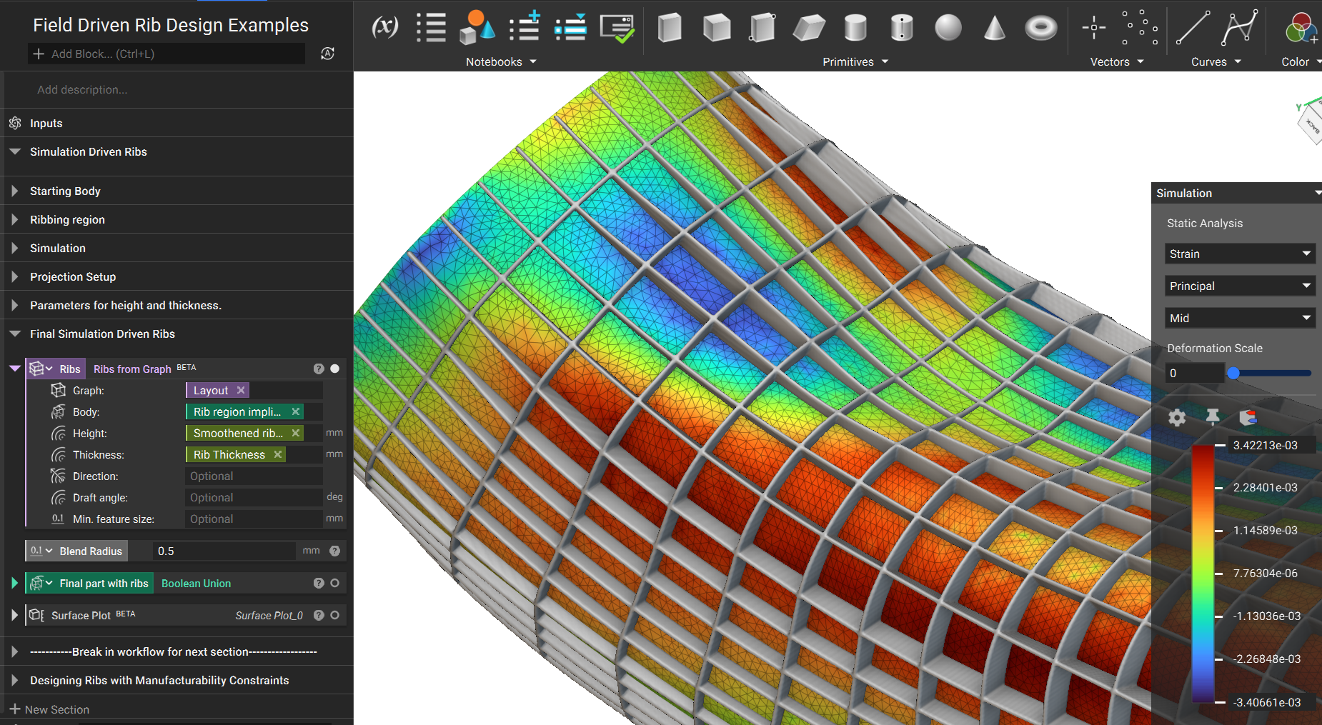
2. Rib geometry can be Field-Driven. In this example, we will run a Static Analysis to generate the field. Torsion is applied using displacement and point restraints. In the following steps, we will use the mid-principal strain field.
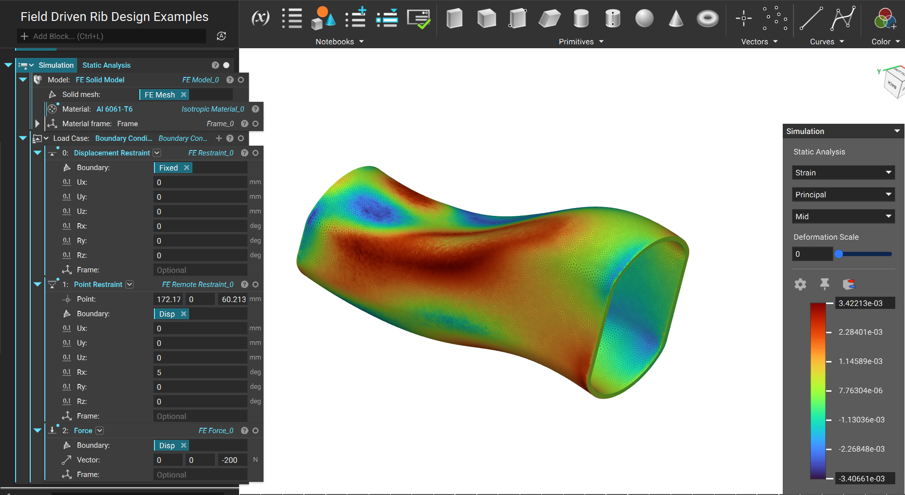
3. To find the maximum and minimum values, evaluate the absolute value of the mid principal strain field at the vertices of the surface mesh. These vertices can be found in the properties of the FE Volume Mesh from CAD block. Then, calculate the max and min values using Max and Min blocks.
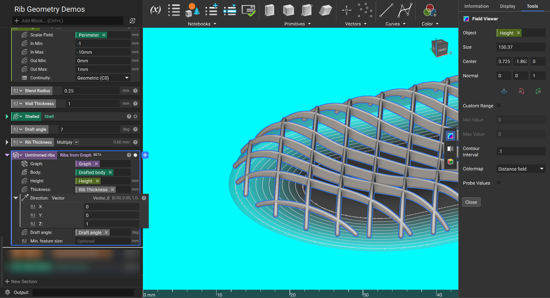
4. As shown in the image below, use a Ramp block to create a height ramp from the strain field. This will map the minimum value to the minimum height and the maximum value to the maximum height.
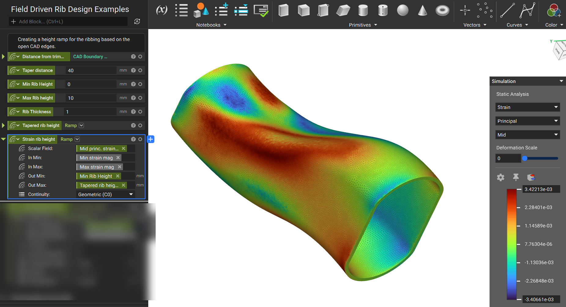
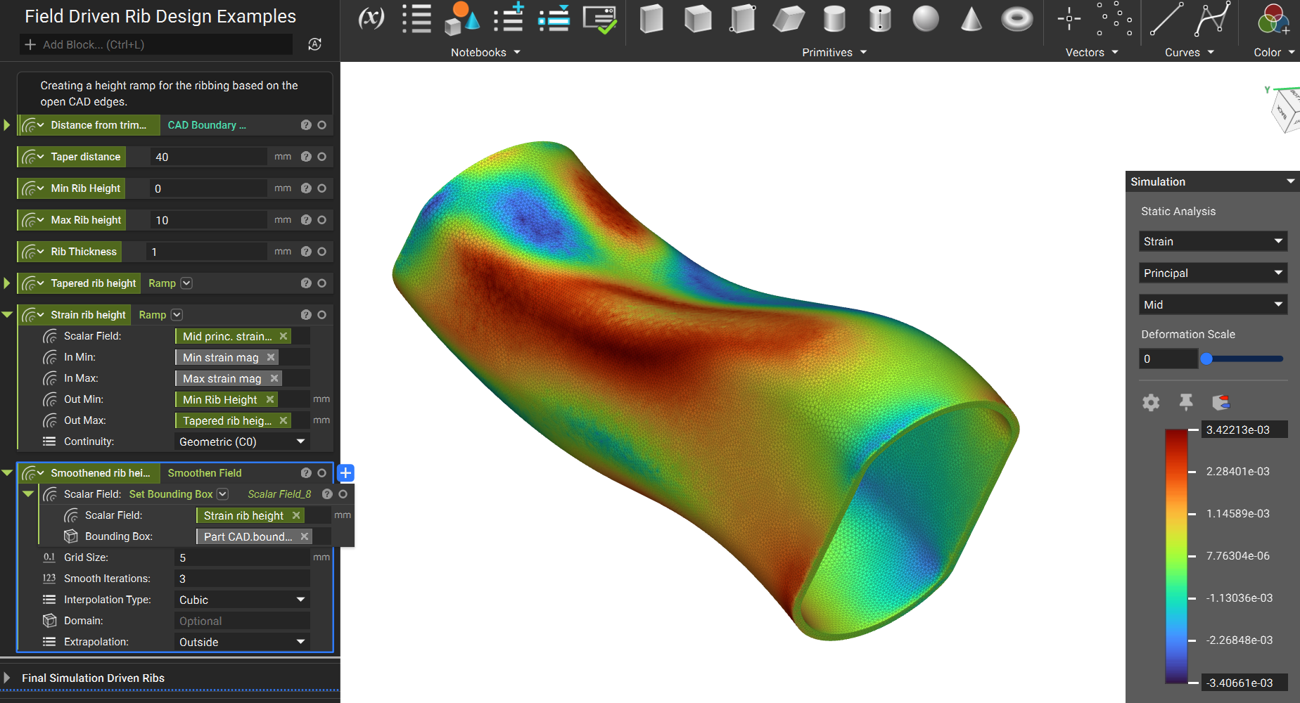
5. Simulation fields can tend to be a bit noisy, so it’s helpful to smoothen the field to create smooth ribs.
6. Use this field in the Height input of the Ribs from Graph (BETA) block. The rib height will now vary with the simulation data.
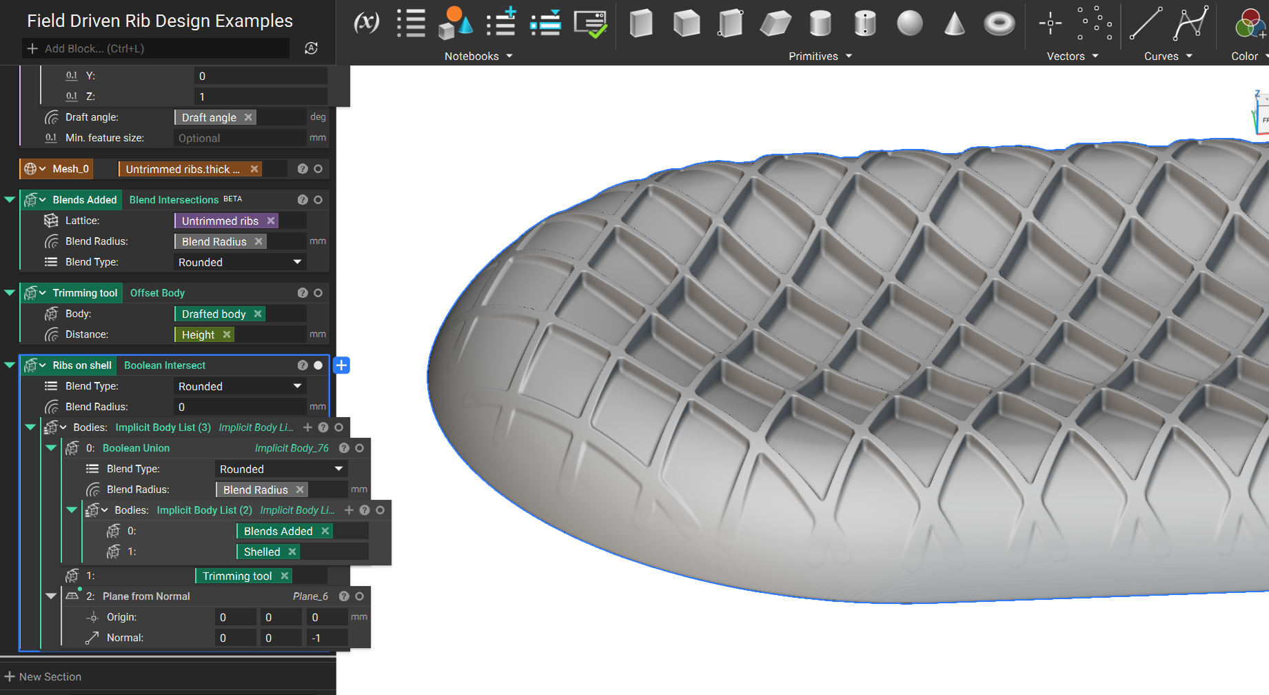
Designing Ribs with Manufacturability Constraints
This section will show how to create a custom extrusion direction, add a draft to the ribs, and add blend radii to the ribs' intersections.
1. Start by creating a graph and, in this case, using planar projection.
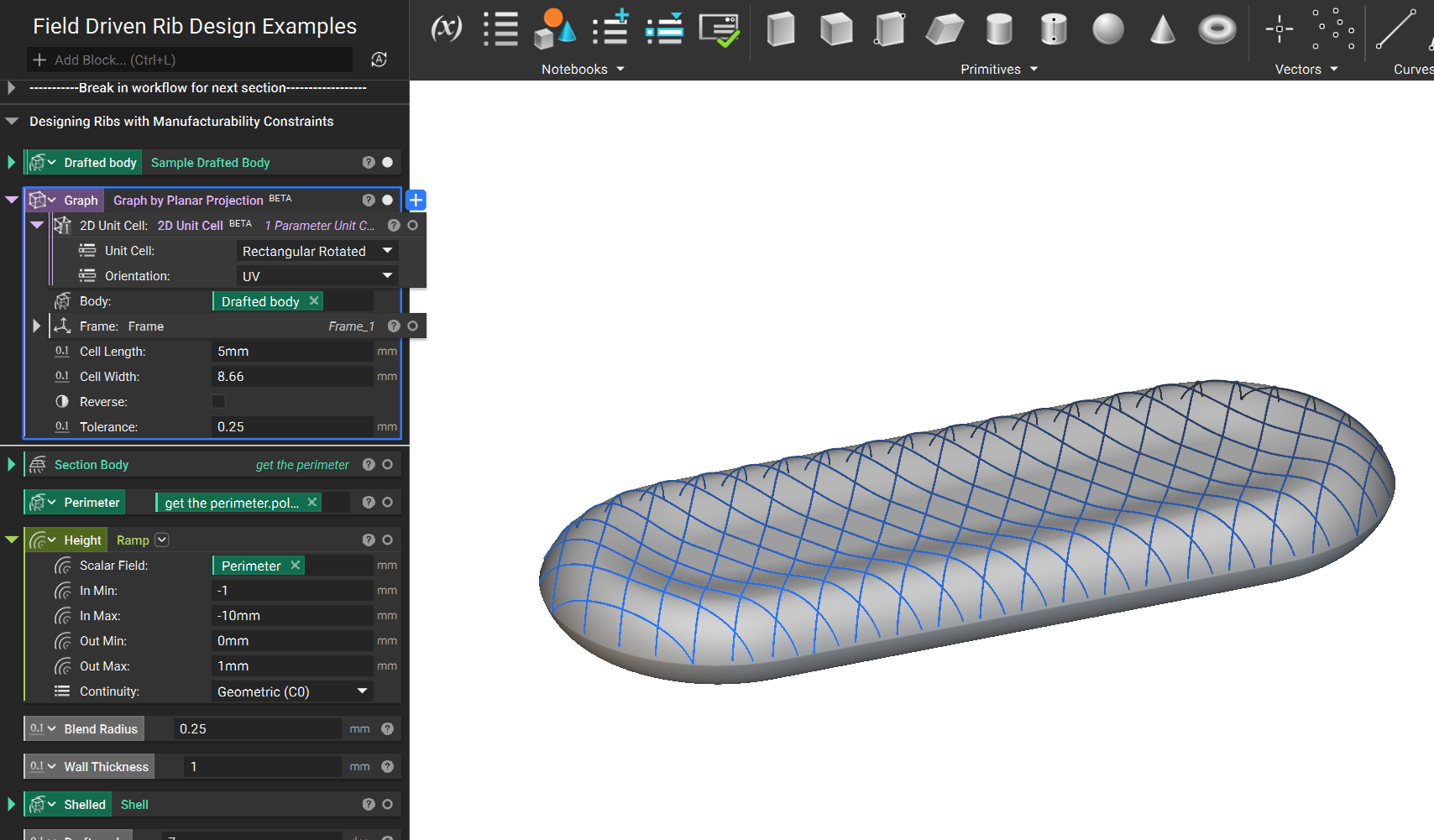
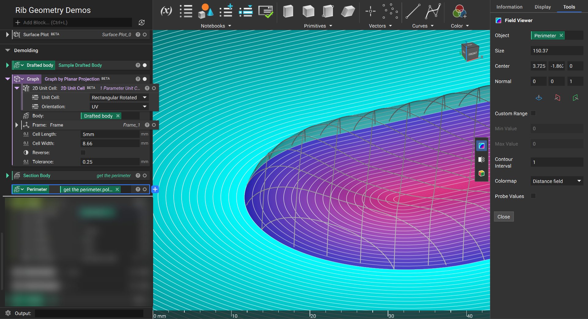
2. We want to create a height ramp that tapers off toward the perimeter. To do this, use Section Body and extract the Polygon -> Body property. This will provide a distance field to the boundary.
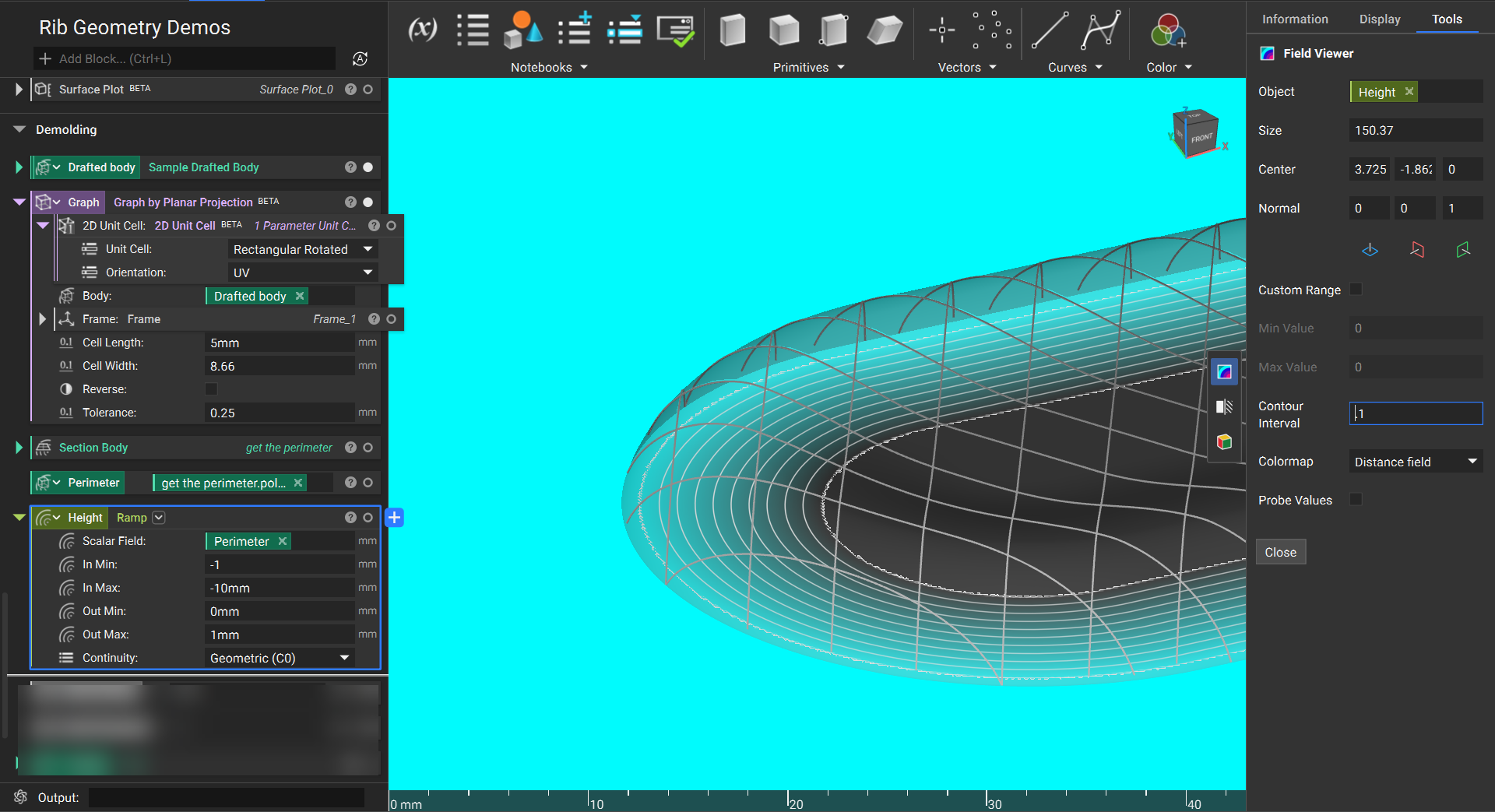
3. Use a Ramp block to turn this distance field into a height ramp.
4. Insert this Ramp into the Height input of a Ribs from Graph (BETA) block to create variable height ribs.
5. The Draft angle input will add a draft from the base of the ribs to the tops. Additionally, the Direction input can override the default extrusion direction (normal to the Body), ensuring a constant extrusion in the Z direction.
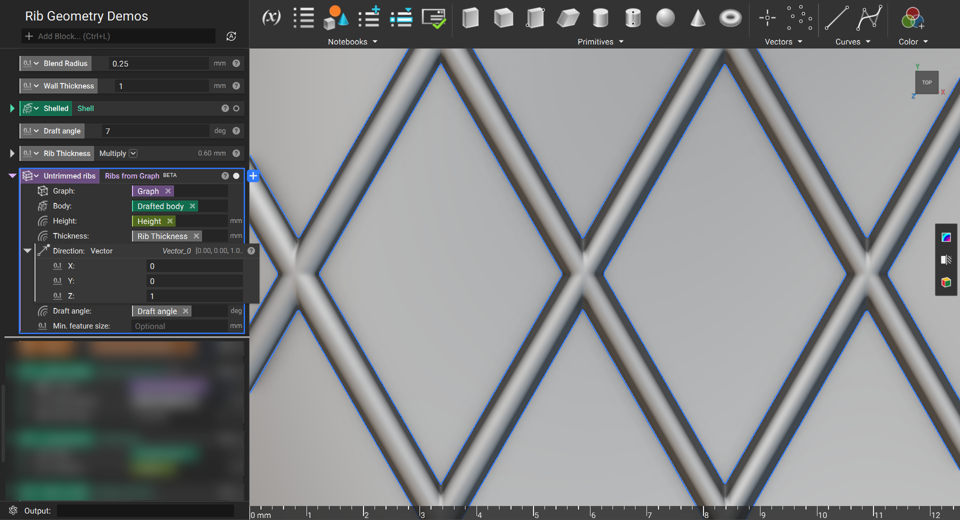
6. Use the Blend Intersections (BETA) block to add blends where ribs intersect. This will create a bulge on the top and bottom, which must be trimmed off.
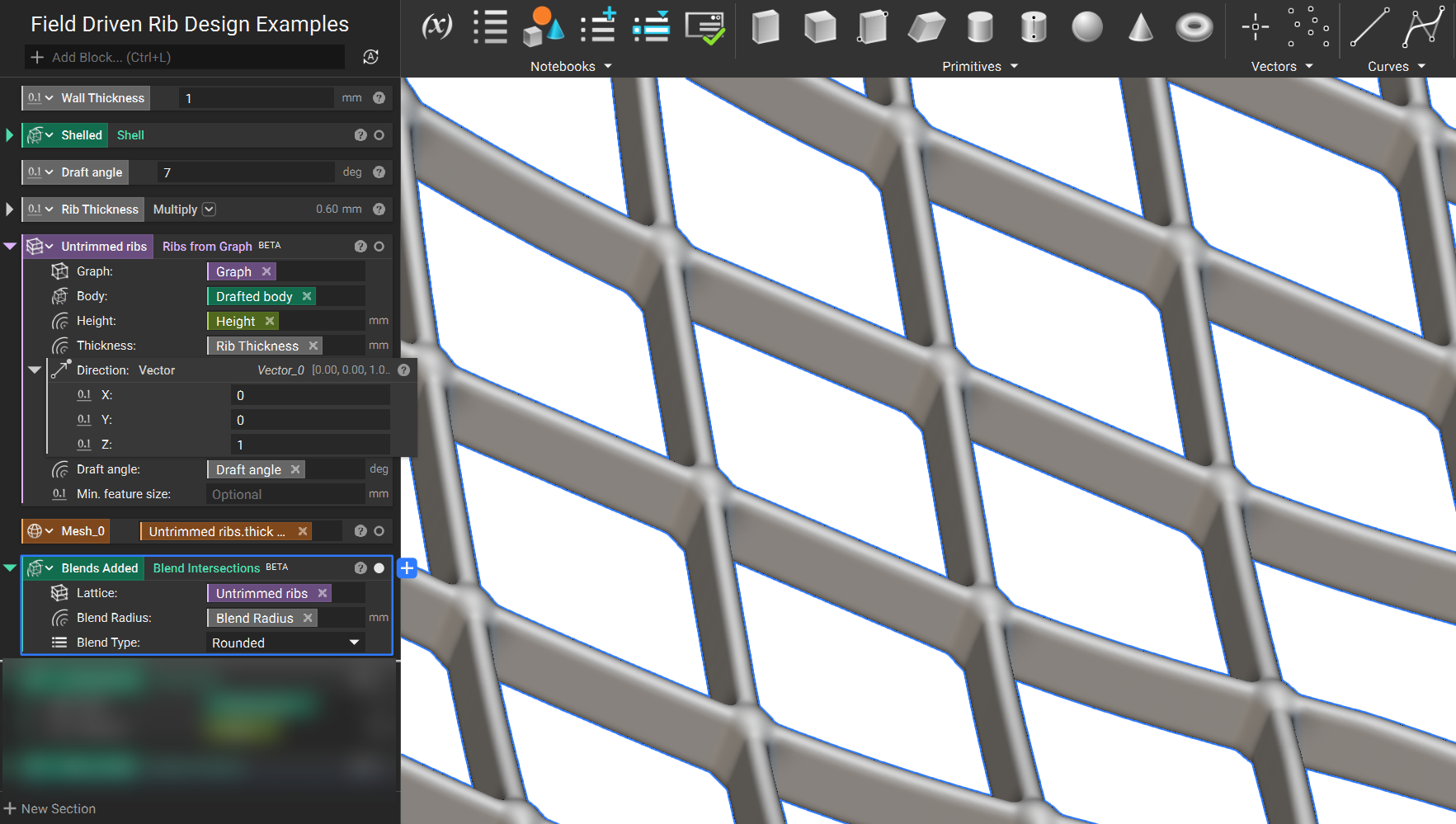
7. Offset the body using the same height ramp used for the ribs.
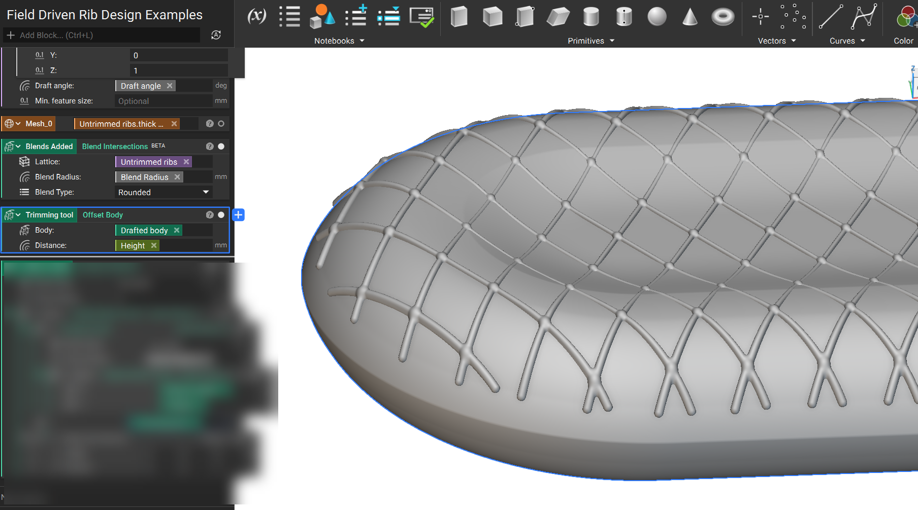
8. Intersect this trimming tool with the ribs to create ribs with flat tops at the specified height. Then, a union with the desired base geometry is performed.