nTop 5.10 is here! This release comes with two new major features. Rib Design blocks allow you to project conformal patterns and then extrude the patterns into solid ribs. We are also introducing our new Surface Analysis view tool for overhang and draft angle inspection. As with every release, nTop’s dedicated support team is ready to answer your questions. Please visit support.ntop.com to gain access to helpful tutorials and support articles.
Rib Design [Beta] Tab
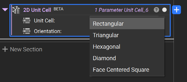
2D Unit Cell
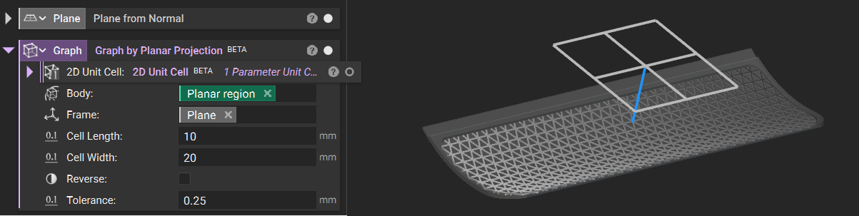
Graph by Planar Projection
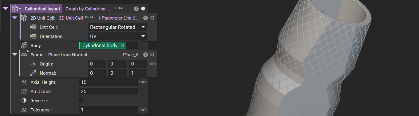
Graph by Cylindrical Projection
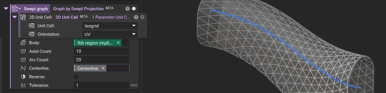
Graph by Swept Projection
Graph on CAD Face
Graph on Quad Mesh
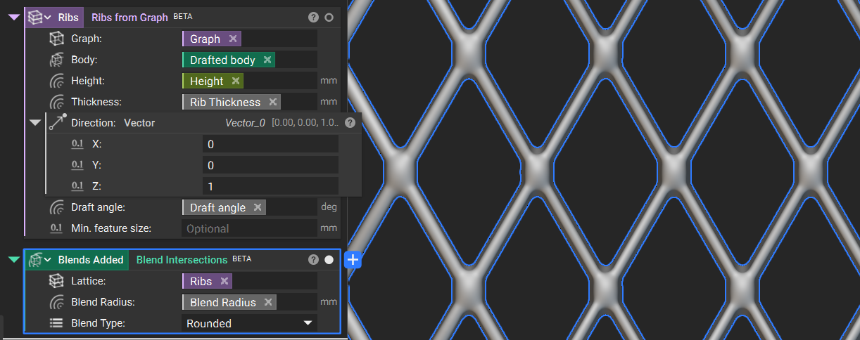
Ribs from Graph
Blend Intersections
Enhanced View Tools with new Draft and Overhang Angle Inspection
Property Highlighting
Rib Design [Beta] Tab
- We added a new ribbon tab called Rib Design [Beta]. This tab includes all the recommended blocks for Rib Design workflows.
- Go to File > Settings to enable Beta blocks and check the Show Beta Blocks box.
2D Unit Cell
- The 2D Unit Cell block provides common 2D tessellation patterns as graph unit cells. The beams are located on one face of the domain and are designed for use in ribbing workflows.
- Location: Rib Design [Beta] > Create
- Description: The selected Unit Cell for the graph generation workflow. This block is used as an input to graph projection blocks or “Periodic Lattice” on a CAD face or quad mesh.
- Unit Cell: The selected unit cell for tessellation.
- Orientation: The in-plane orientation of the unit cell.
- Output: Volumetric Rule
Graph by Planar Projection
- The Graph by Planar Projection block projects a graph in a constant direction to an implicit body.
- Workflows: Rib Design Surface Latticing
- Location: Rib Design [Beta] > Create
- Description: Creates a graph on the surface of an implicit body with planar projection.
- 2D Unit Cell: Pattern used to create the graph on the body.
- Body: Body on the surface of which to create the graph.
- Frame: Frame that defines the orientation of the projection mapping.
- Cell Length: Cell size in the length (Frame X axis) direction.
- Cell Width: Cell size in the width (Frame Y axis) direction.
- Reverse: Reverse the direction of projection.
- Tolerance: Minimum feature size to accurately capture the boundary.
- Output: Graph
Graph by Cylindrical Projection
- The Graph by Cylindrical Projection block projects a graph along a radial direction to an implicit body.
- Workflows: Rib Design Surface Latticing
- Location: Rib Design [Beta] > Create
- Description: Creates a graph on the surface of an implicit body with cylindrical projection. To set the map’s orientation and position, use the Frame input.
- 2D Unit Cell: Pattern used to create the graph on the body.
- Body: Body on the surface of which to create the graph.
- Frame: Frame that defines the orientation of the projection mapping.
- Axial Height: Cell size in the axial direction.
- Arc Count: Number of cells in the circumferential direction.
- Reverse: Reverse the direction of projection.
- Tolerance: Minimum feature size to accurately capture the boundary.
- Output: Graph
Graph by Swept Projection
- The Graph by Swept Projection block projects a graph along a radial direction relative to a centerline curve to an implicit body.
- Workflows: Rib Design Surface Latticing
- Location: Rib Design [Beta] > Create
- Description: Creates a graph on the surface of an implicit body with curved cylindrical projection based on a centerline curve. projection. To set the map’s orientation and position, use the Frame input.
- 2D Unit Cell : Pattern used to create the graph on the body.
- Body: Body on the surface of which to create the graph.
- Frame: Frame that defines the orientation of the projection mapping.
- Axial Count: Number of cells in the axial direction.
- Arc Count: Number of cells in the circumferential direction.
- Centerline: Curve that defines the centerline of the projection mapping.
- Reverse: Reverse the direction of projection.
- Tolerance: Minimum feature size to accurately capture the boundary.
- Output: Graph
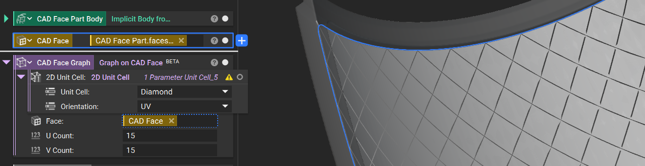
Graph on CAD Face
- This Graph on CAD Face block creates a periodic graph following the UV parameterization of a CAD face.
- Workflows: Rib Design Surface Latticing
- Block Name: Graph on CAD Face
- Location: Rib Design [Beta] > Create
- Description: Creates a conformal graph to a CAD face.
- 2D Unit Cell : Pattern used to create curves on the CAD face.
- Face: Face on which to conform the graph.
- Frame: Frame that defines the orientation of the projection mapping.
- U Count: Number of cells in the U direction.
- V Count: Number of cells in the V direction.
- Output: Graph
Graph on Quad Mesh
- The Graph on Quad Mesh block creates a periodic graph on the faces of a quad mesh.
- Workflows: Rib Design Surface Latticing
- Location: Rib Design [Beta] > Create
- Description: Creates a graph that is conformal to a quad mesh. Note that the U and V orientations of individual cells will not be continuous.
- 2D Unit Cell: Pattern used to create curves on the CAD face.
- Face: Face on which to conform the graph.
- Quad Mesh: Quad mesh that the graph will be generated from.
- Output: Graph
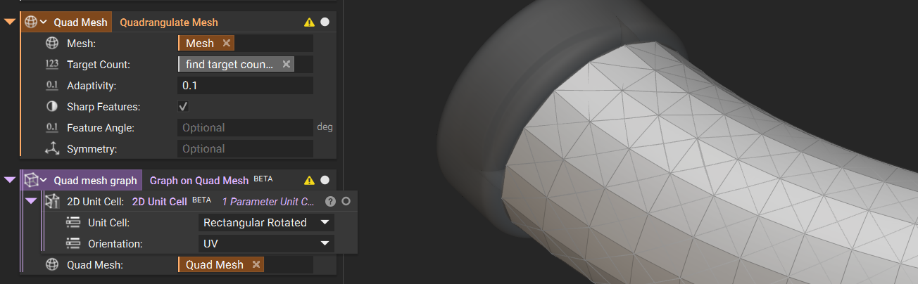
Note: The U and V orientations of individual cells will not be continuous.
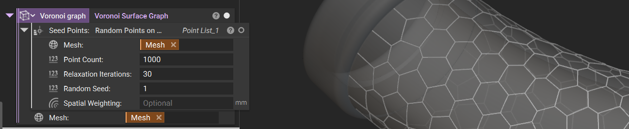
Voronoi Surface Graph
- The Voronoi Surface Graph block creates a Graph from the Voronoi Diagram of a list of Points restricted to the surface boundary of a body.
- Workflows: Rib Design Surface Latticing
- Location: Rib Design [Beta] > Create
- Description: Creates a Graph from the Voronoi Diagram of a list of Points restricted to the surface boundary of a body.
- Seed Points: List of Points to generate the Voronoi Graph from.
- Mesh: Mesh to generate the Voronoi Graph on.
- Output: Graph
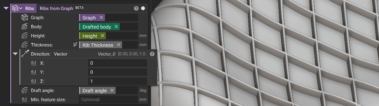
Ribs from Graph
- The Ribs from Graph block creates extruded ribs from a graph on an implicit body surface in a custom extrusion direction.
- Workflows: Rib Design
- Location: Rib Design [Beta] > Create
- Description: Create extruded ribs from a graph on an implicit body surface, and custom extrusion direction.
- Graph: The graph to extrude into ribs
- Body: The body on which the ribs will be joined downstream. This body determines the extrusion height in combination with the “Height” input.
- Height: Rib height.
- Thickness: Rib thickness.
- Direction: The direction to extrude the ribs. To create ribs that follow the Body’s normals, use the same input as the “Body” input. To use a custom direction, use another body, such as an axis or plane.
- Minimum feature size: Minimum feature size to accurately capture boundary.
- Output: Lattice
Blend Intersections
- The Blend Intersections block adds a blend radii between lattice beams to create a smoother transition.
- Workflows: Rib Design
- Location: Rib Design [Beta] > Modify
- Description: Add blend radii between lattice beams.
- Lattice: The lattice to add blend radii to.
- Blend Radius: Blend radius to apply to lattice vertices.
- Blend Type: Type of blend between the lattice elements.
- Output: Implicit Body
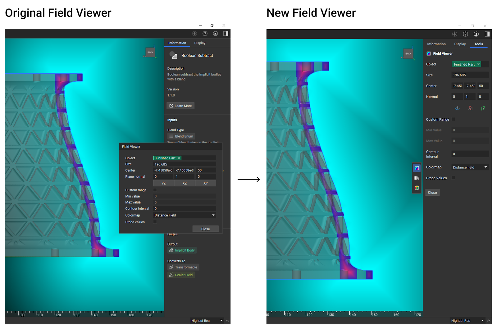
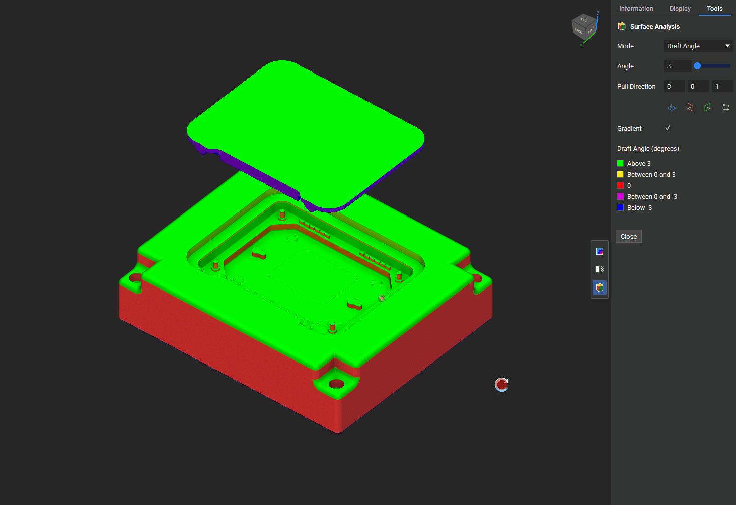
Enhanced View Tools with new Draft and Overhang Angle Inspection
- The View Tools provide visualization options for inspecting geometry directly in the viewport, including the Section Cut and Field Viewer and the new Surface Analysis tool for overhang and draft angle inspection.
- Location: The tools can be accessed with a new toolbar on the right side of the viewport or via the standard keyboard shortcuts. When a tool is activated, its settings appear in a new ‘Tools’ tab in the Right Panel, and the tool is highlighted in the toolbar.
- Overhang Angle
- The overhang angle colors regions of your model where angles may exceed the printable threshold, helping you verify the design and identify regions needing support.
- Draft Angle
- The draft analysis visualization colors areas of your model based on a specified draft angle relative to a pull direction (the draw direction of the mold), helping you verify that your design meets manufacturability requirements
Property Highlighting
- Upon hovering, this update displays a preview of each property in the viewport, providing immediate visual feedback as you navigate the properties panel. This will help you identify properties that you’re looking for and determine the location of geometry without dragging it into the notebook.
- Tip: we recommend setting the object to transparent when looking for properties in the view because the properties could be inside the object and may not be visible depending on your view. You can hide the object entirely, and the properties will remain displayed.
- Note: The display of properties is limited to rendering performance, so it will display data types, including points, bounding boxes, line segments, arcs, circles, planes, and frames. It will display lists of these types up to 10,000 items, and lists over 10,000 will not appear on hover. It will also display individual items for axes, curves, polygons, and slices, but not lists. All other types will not display to preserve rendering performance.