Question:
How do I access block properties and info?
Answer:
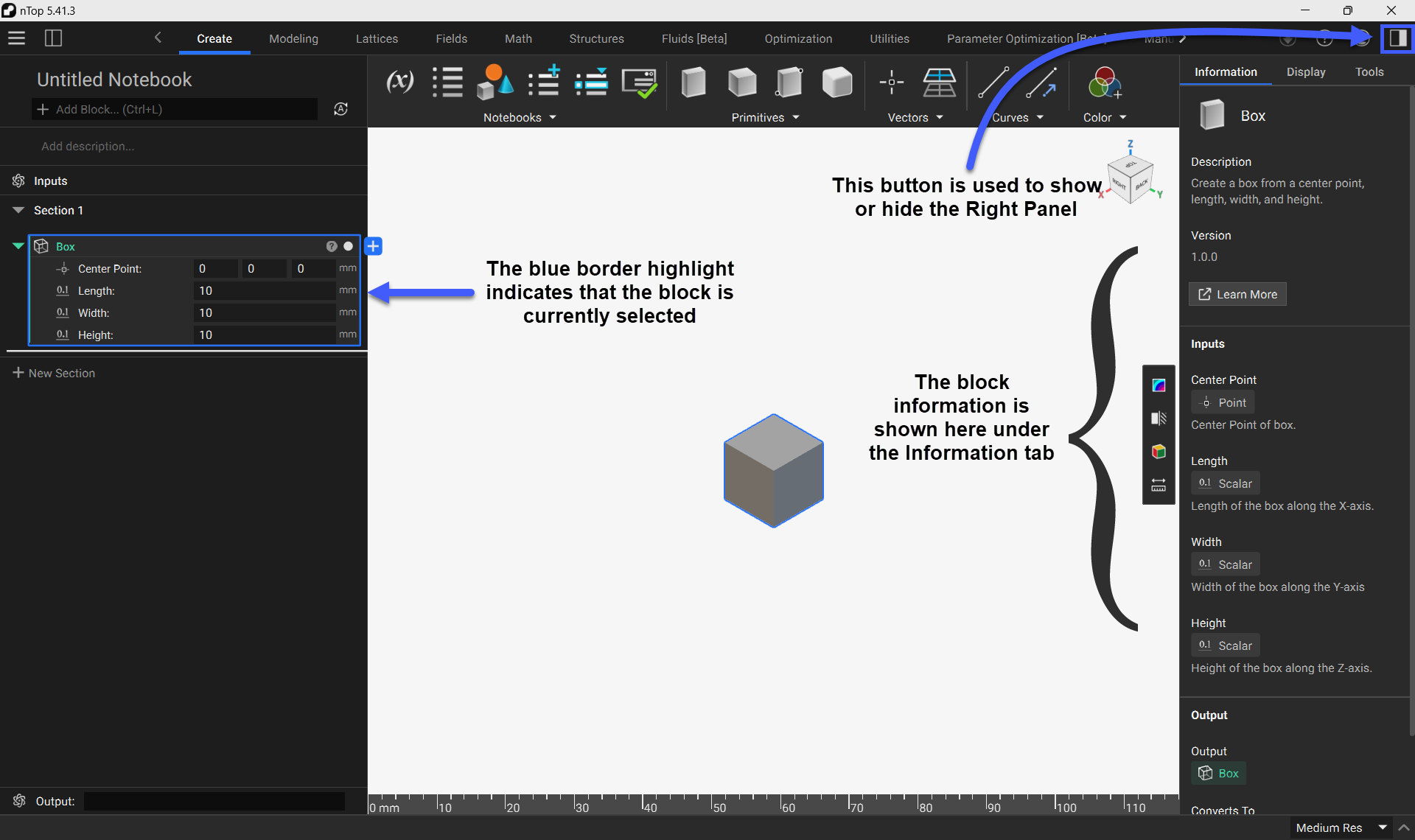
Information Tab
You can access a block's information by selecting the block and opening the Right Panel. The block's information is shown under the Information tab. The Information Tab contains:
- Block Description
- Version Number
- Input Descriptions
- Output Description
- Conversion Information
Display Tab
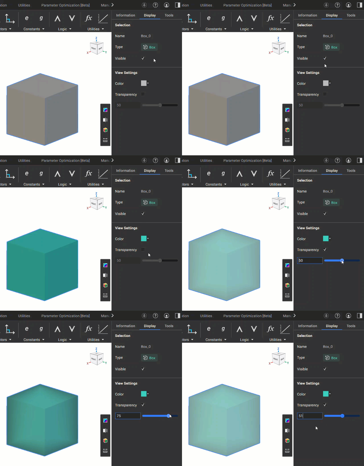
You can modify a block's appearance by selecting the block and opening the Display Tab in the Right Panel. The Display Tab contains:
- Block Name
- Block Type
- Visibility toggle
- Color Settings
- Transparency Control
Tools Tab
The Tools tab will display the tool functionality that is selected from the View Tools Sidebar.
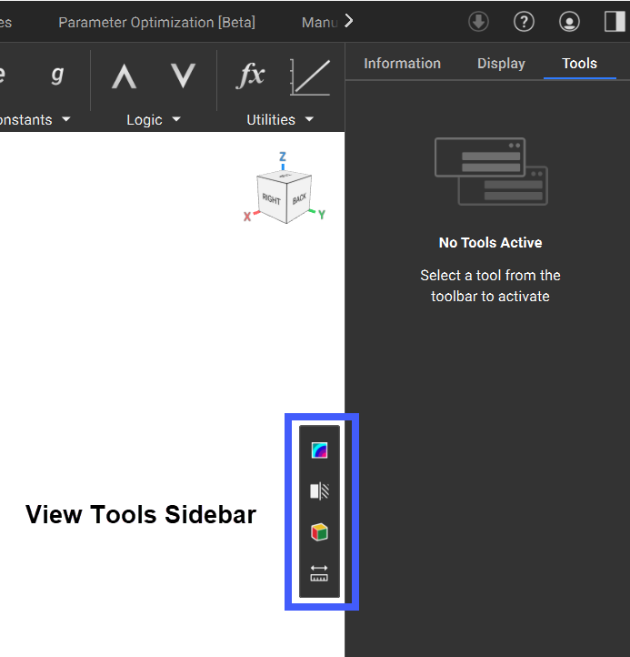
The View Tools Sidebar contains several helpful tools for analyzing your geometry:
-
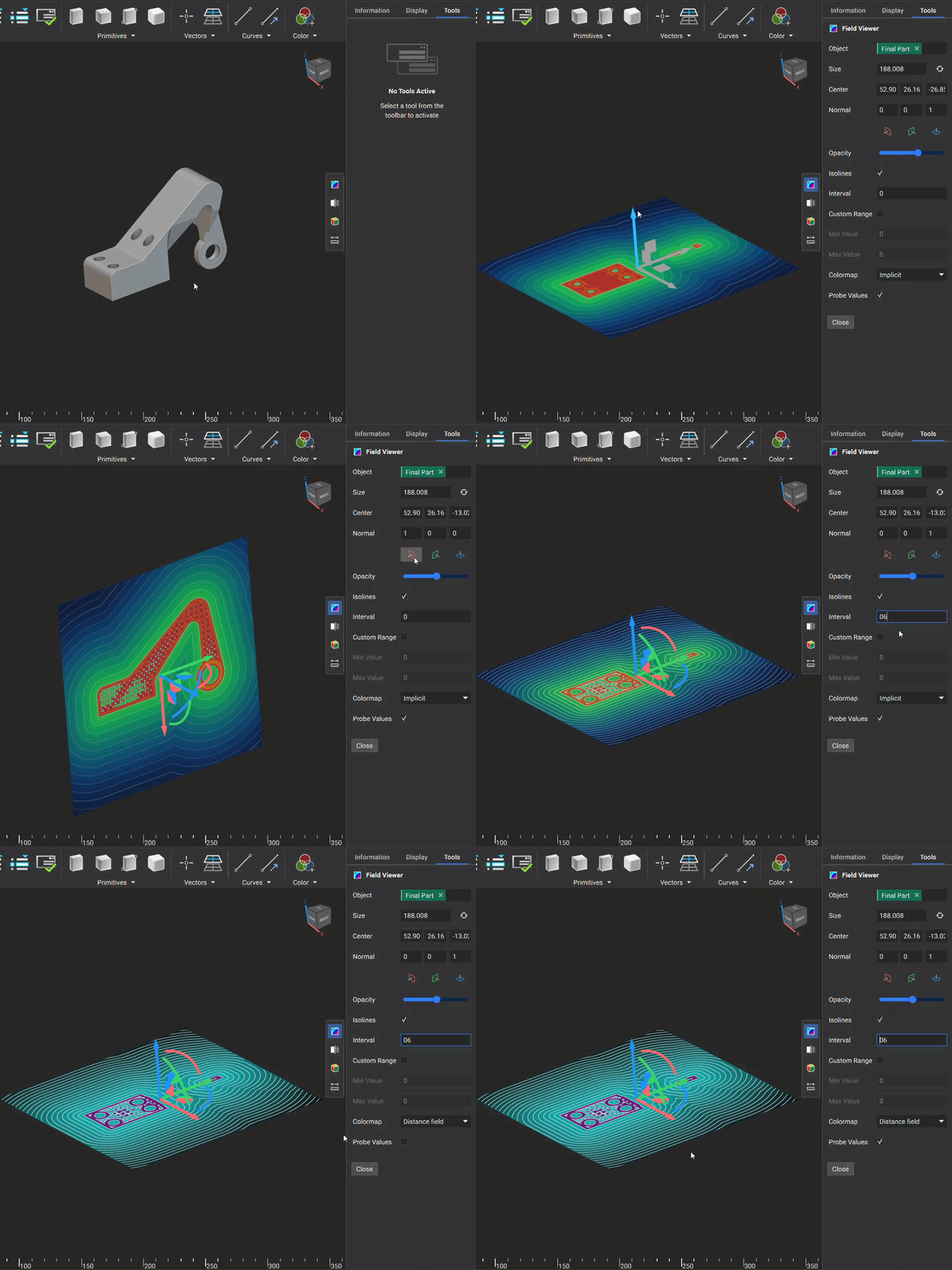
Field Viewer: The Field Viewer allows you to visualize a field. You can change the plane of visualization using the colored plane icons. The following options are available to analyze the field:
- Opacity: Changes the opacity of the visualized field
- Isolines: Option to turn on/off the isolines
- Interval: Changes the spacing between the isolines
- Custom Range: Option to manually specify the value range of the field
- Min Value: Minimum value when a Custom Range is applied
- Max Value: Maximum value when a Custom Range is applied
- Colormap: Option to change the color scheme of the field
- Probe Values: Toggles the ability to see field values when moving the mouse over the field
-
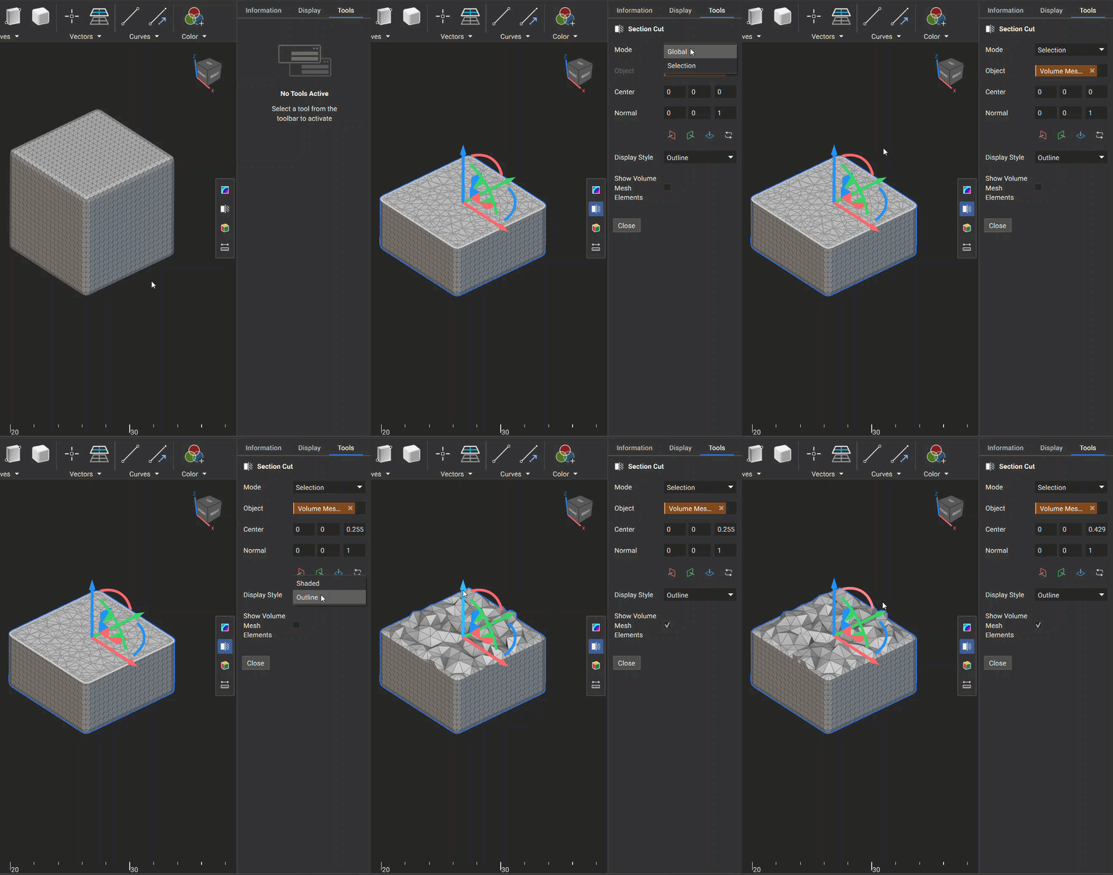
Section Cut: This tool is used to cut geometry at a specified plane. You can change the plane of visualization using the colored plane icons. The following options are available when performing a section cut:
- Mode: Choose between performing a section cut on a specific body (Selection) or on all visualized bodies that intersect the plane (Global)
- Display Style: Changes the display style of the sectioned body
- Show Volume Mesh Elements: If the body is a volume mesh, you can toggle the visualization of the 3D internal volume elements
-
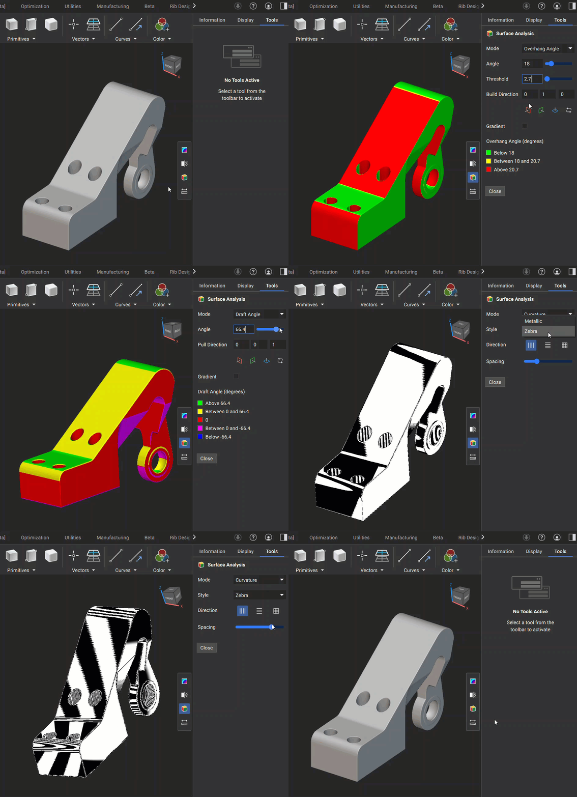
Surface Analysis: The Surface Analysis tool has three different modes you can use to analyze the surface of your geometry:
-
Overhang Angle: This mode is used to identify regions in your model where angles may exceed the printable threshold, helping you inspect the design for additive manufacturability. It has the following options for inspection:
- Angle: The lower value of the angle analysis
- Threshold: The range between the lower and upper angle values being evaluated
- Build Direction: Specifies the build plane normal direction
- Gradient: Option to display the color scheme as gradient or not
-
Draft Angle: This mode visualizes areas of your model based on a specified draft angle relative to a pull direction, helping you verify that your design meets manufacturability requirements. It has the following options for inspection:
- Angle: The specified angle to evaluate the geometry
- Pull Direction: The plane used to specify the angle relative to the geometry
- Gradient: Option to display the color scheme as gradient or discrete
-
Curvature: This mode is used to analyze the curvature of a geometry’s surface.
- Metallic: Renders the geometry with a shiny, reflective surface, which improves the clarity of curvature and surface quality.
- Zebra: Displays a series of alternating black and white stripes on a surface. The reflection patterns of these stripes help visualize the surface’s curvature. You can select from three buttons to choose the orientation of the stripes and use a slider to adjust their spacing.
-
Overhang Angle: This mode is used to identify regions in your model where angles may exceed the printable threshold, helping you inspect the design for additive manufacturability. It has the following options for inspection:
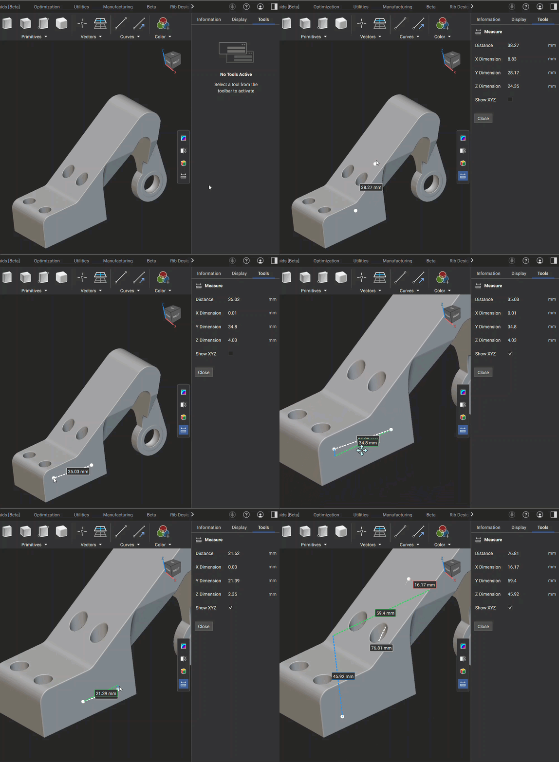
- Measure: The Measure Tool lets you directly measure distances between two points within your 3D model. This feature is ideal for quick inspections and supports interactive visualization of distances along global X, Y, and Z axes. The total distance and XYZ dimensions appear in the Right Side Panel, and you can check the “Show XYZ” checkbox to display dimension lines for X, Y, and Z in the 3D view.
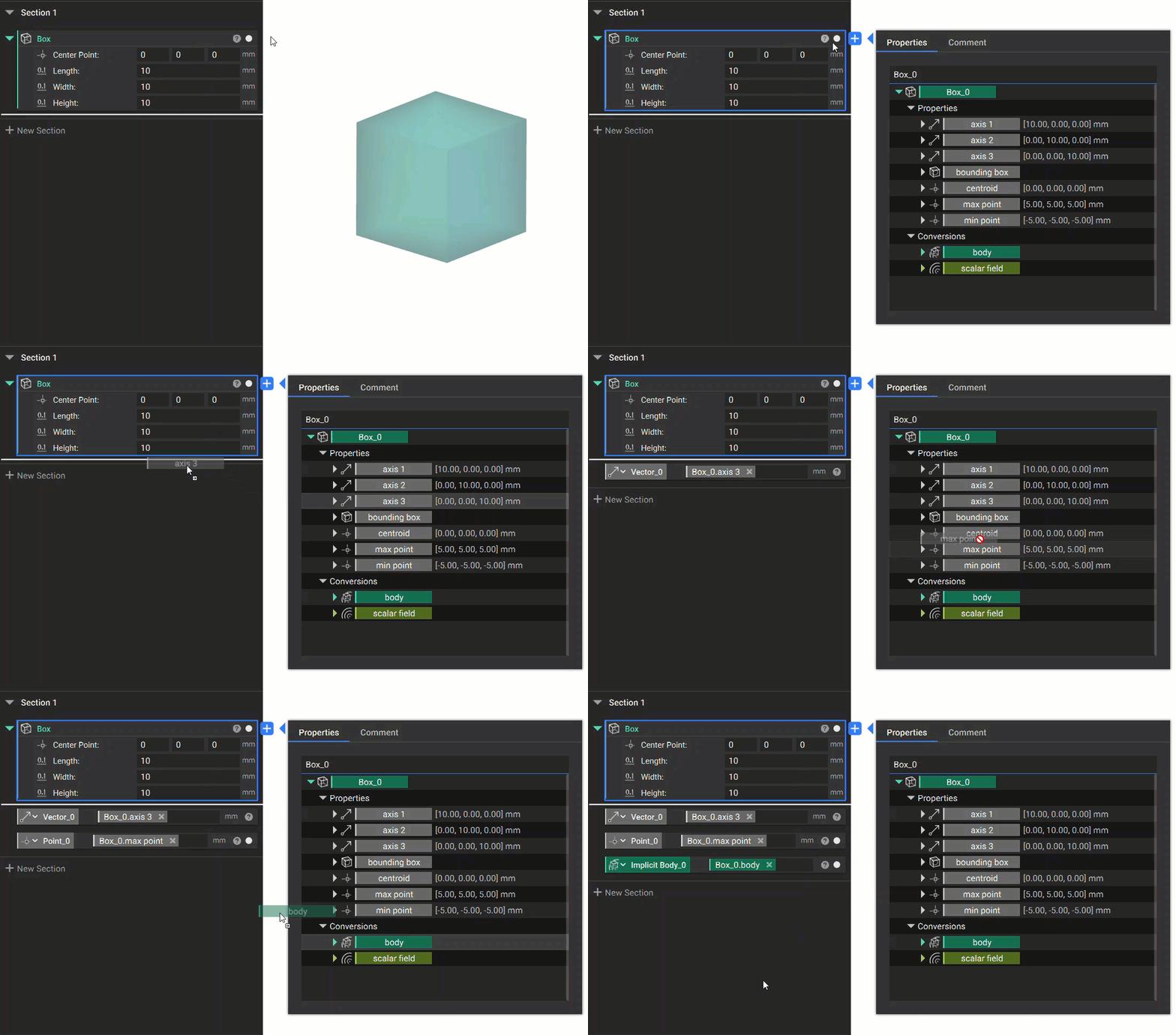
Properties Panel
A block's Properties Panel gives you access to different properties the block contains. These properties vary depending on the type of block. Property chips can be dragged into the notebook and used as variables. You can access the Properties Panel by clicking the question mark icon in the top right corner of the block.