Objective:
Learn how to set up a thermal analysis with all available boundary conditions and use the resulting temperature field to perform a thermal stress analysis in the same nTop Notebook.
Procedure:
1. Defining Material Properties
If you would like to learn more about creating different Materials, I suggest checking this article: How to create a material in nTop
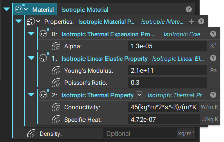
To set up a material for thermal analysis, a thermal material property block must be added to the Properties list of a Material. These include conductivity and specific heat. Young’s Modulus and Poisson’s ratio are needed for Static Analysis without thermal stress. If the static analysis includes thermal stress, a third property, the Isotropic Thermal Expansion Property, must be added, including the thermal expansion coefficient (CTE).
2. Thermal Analysis
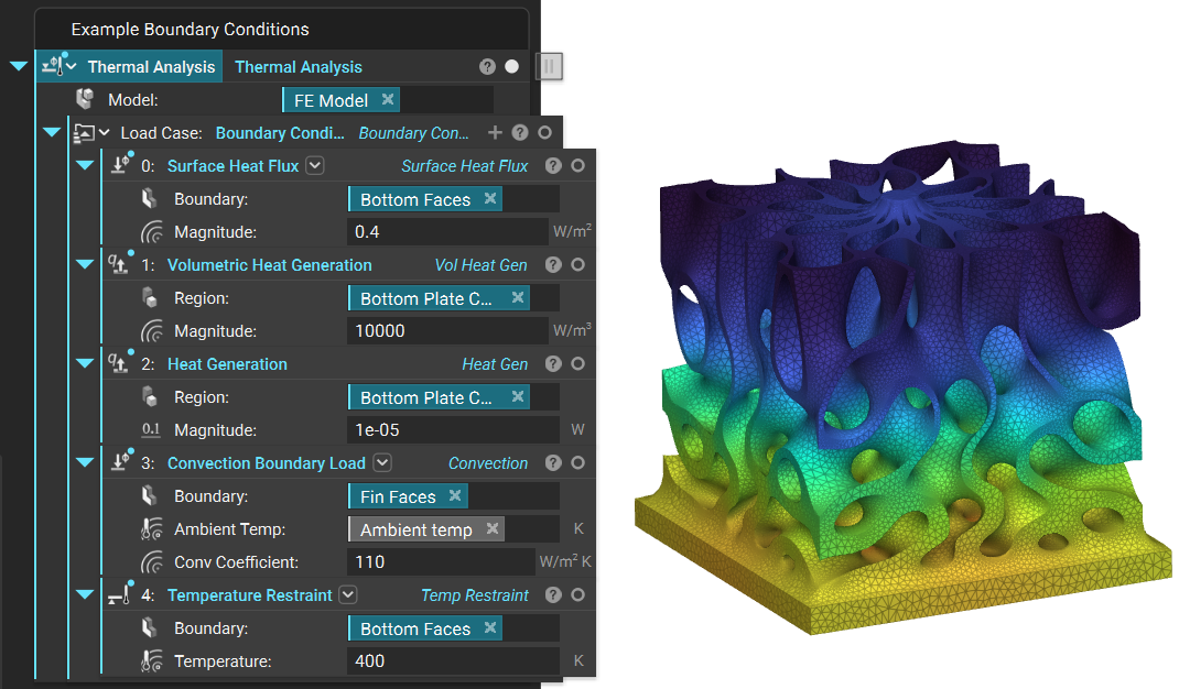
The Thermal Analysis block consists of a Model input and a Boundary Condition List. The available boundary conditions for thermal analysis are listed below.
For more information on each boundary condition block and its inputs, click on the Info Panel (the gray question mark on the right side of the block).
Available Boundary Conditions
- Heat Generation
- Volumetric Heat Generation
- Surface Heat Flux
- Radiation Boundary Load
- Convection Boundary Load
- Temperature Restraint
Note: The Radiation Boundary Load is only supported in the Nonlinear Thermal Analysis block.
3. Obtaining a Temperature Field from Thermal Analysis
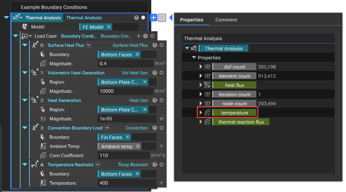
Once the thermal analysis is complete, the resulting temperature is viewable through the HUD, and The Temperature field chip can be dragged from the properties of the Thermal Analysis block.
4. Thermal Stress Analysis
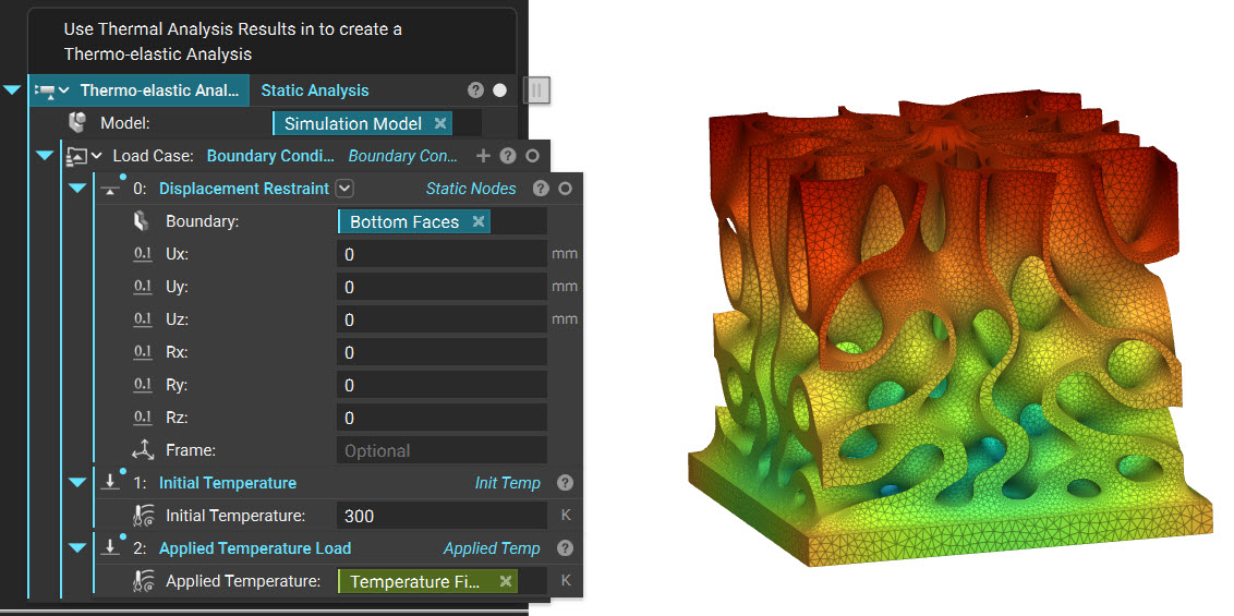
A thermal load can be applied to a Static Analysis just like any other structural boundary condition (such as forces, pressure, and displacement restraints) with the temperature field defined. The applied temperature load will cause the material to expand and contract based on its CTE. An initial temperature load can be applied as a reference point for the initial expansion before the temperature load is applied and should usually be set to the ambient temperature of the part before thermal loading.
Available Boundary Conditions
- *Any structural boundary condition*
- Applied Temperature Load
- Initial Temperature
And that’s it! You’ve successfully run a thermal analysis.
Do you still need help? Contact the support team, and we’ll be happy to help!