Objective:
Learn how to create a Simulation Model that has more than one material.
Applies to:
- Simulation
- Topology Optimization
Procedure:
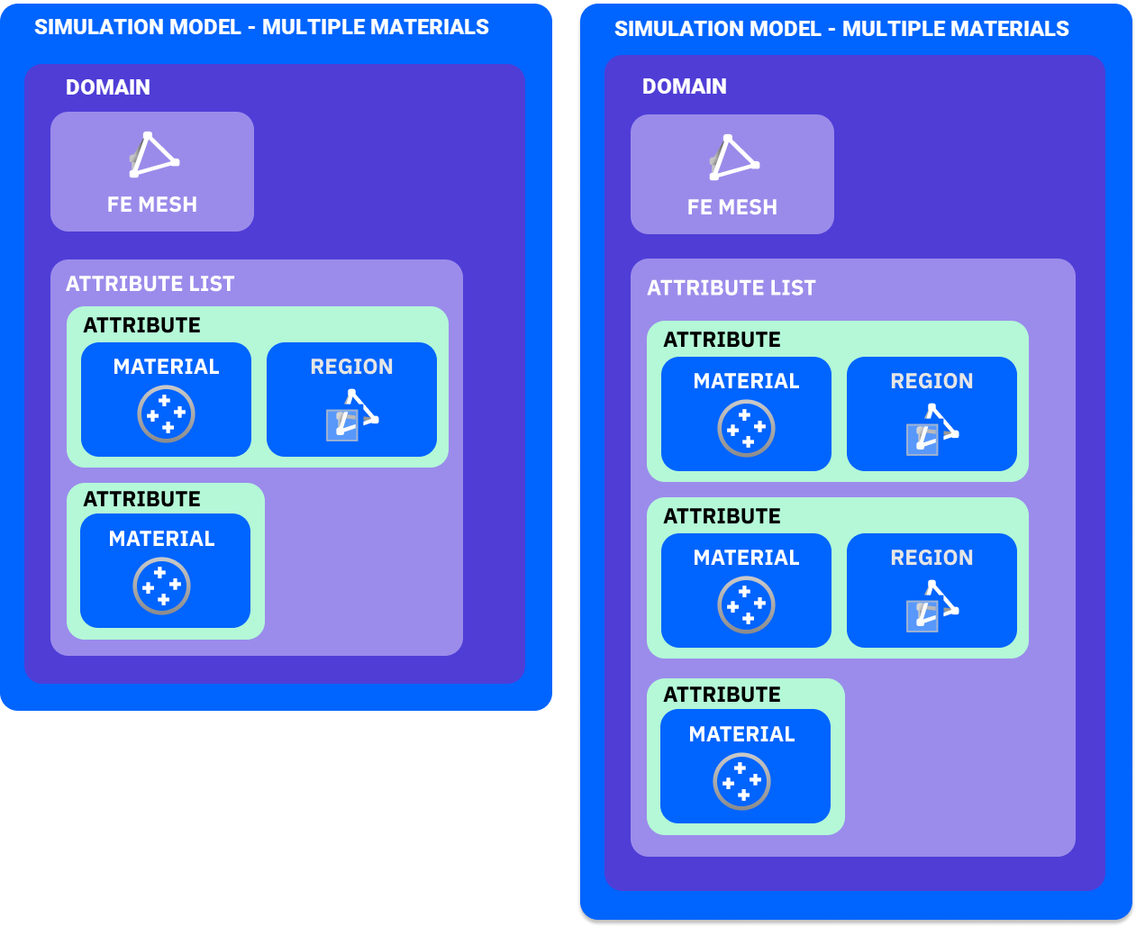
Material is applied to a Simulation Model by using Attributes. Each Attribute adds a new material. To add more than one material to a Simulation Model, you need a Region to define where that material is applied. If you only have two attributes, then one of them doesn't need a Region. Instead, that material will be applied everywhere the other material isn't. Check out the image below to see how you would set up two and three material attributes.
1. Set-Up: Download the example file and start with the FE Mesh already created.
2. Simulation Model:
-
- Add a Simulation Model block.
- Add a Solid Domain.
- Input the FE Mesh variable.
- Click the + on the Attribute List to add another Attribute.
- Input a Solid Attribute into each input in the Attribute List.
3. Material:
-
- In the first Solid Attribute, add the Al 6061-T6 Material to the Material input.
- Add the Stainless Steel 316 material to the second Solid Attribute.
- An error will pop up saying you need to set a Region for one of the Attributes.
4. Region:
-
- Add an FE Region by Body in the second Solid Attribute.
- Set the Mesh to the FE Mesh variable.
- Set Entity to Cells.
- Set Body to the Grip Implicit Body variable.
This will set the Grip part to be Stainless Steel, and set the rest of the pen body to be Aluminum.
And that’s it! You’ve successfully set up a Simulation Model with multiple materials.
Are you still having issues? Contact the support team, and we’ll be happy to help!