Table of Contents:
1.0 Why is this change happening?
2.0 Key concepts and principles
3.0 What you'll notice first
4.0 Changes to boundary conditions
5.0 Changes to FE Point
6.0 New blocks and types for CFD
7.0 How to update blocks that did not automatically update
8.0 Recovery results from previous versions
9.0 What's next
Appendix: Summary of block and type changes
1.0 Why is this change happening?
In nTop 5.23, the simulation workflow has been expanded to support a growing range of Multiphysics simulation capabilities in nTop, including the recent addition of computational fluid dynamics (CFD). This update ensures a consistent setup and execution experience across different physics types. Unlike the existing structural analyses that rely on body-fitted volume meshes, the new CFD technology operates directly on implicit bodies without body-fitted meshes.
Looking ahead, additional “meshless” simulation methods may also be introduced. To prepare for this, the simulation blocks and types have been updated to support direct simulation on implicit geometry while maintaining compatibility with existing mesh- and CAD-based workflows.
Existing nTop files will continue to run as expected. Most blocks will update automatically without affecting notebook behavior. Other blocks with new behavior have been versioned to ensure compatibility. When opening a file from a previous version, the notebook will retain the older block versions, which can be updated when convenient.
2.0 Key concepts and principles
Understanding the following guiding principles behind the new block design will make the transition smoother.
There are two model types - FE Model and Virtual Model
If you’ve used nTop before, you’re familiar with the FE Model type, a container for the simulation domain, material properties, and connections between individual components in the domain. This model type still exists and should be used when the simulation domain will be meshed within nTop.
We have introduced a new model type called Virtual Model to support simulations that don’t require meshing in nTop. Instead of relying on a mesh, the simulation domain in a Virtual Model is defined directly by an implicit body, enabling a more flexible and efficient workflow for meshless simulations.
A new Simulation Model block has been introduced with two overloads - one that outputs an FE Model and one that outputs a Virtual Model. The FE Model overload is used to create a simulation model for all mesh-based structural analyses in nTop: Static Analysis, Thermal Analysis, Modal Analysis, Buckling Analysis, Homogenization Unit Cell, Topology Optimization, and Field Optimization. Meanwhile, the Virtual Model overload of the Simulation Model block is used to create a Flow Analysis with the new CFD solver.
Models are composed of domains
A model consists of one or more simulation domains, with connections that define how forces, temperatures, and other physical quantities are transferred between them. Like models, an FE Domain denotes a simulation domain that requires a mesh, and a Virtual Domain denotes a domain defined by an Implicit Body and does not require meshing in nTop.
If you've used nTop before, what was previously called FE Components are now Domains. This change reflects the expanded capabilities of our simulation framework—domains can now be mesh-based or implicit-based and represent solid or fluid regions.
Attributes determine the physics of the domain
The physics to be simulated in the domain is determined by the Attribute assigned to the domain. Solid Attributes are assigned to a Solid Domain, and Fluid Attributes are assigned to a Fluid Domain. Theoretically, a model can include solid and fluid domains, but this is not currently supported.
The inputs to the domain attribute then define material properties and kinematic idealizations (e.g., beam and shell simplifications).
Same boundary conditions, multiple ways to scope them
- In general, boundary conditions consist of two key elements:
The surface or region to which the boundary condition is applied. This is called the scope. - The specific parameters of the condition itself, such as pressure or temperature.
The same boundary conditions can be applied to either an FE Domain or a Virtual Domain. However, each boundary condition is overloaded by the method in which the boundary condition is scoped. There are three ways to scope boundary conditions:
- by CAD Face - supported on both FE Domains and Virtual Domains
- by Body - supported on both FE Domains and Virtual Domains
- by Flood Fill - only supported on FE Domains
See Section 4 for more details on boundary conditions.
3.0 What you'll notice first
You’ll first notice that several simulation blocks and types have been renamed.
First, the FE Model block has been renamed to Simulation Model. Moreover, this block has two overloads, one that creates an FE Model and one that creates a Virtual Model. FE Model is used to create a model from meshed sub-domains, whereas the Virtual Model creates a model from Implicit Bodies. When opening a nTop file from a previous release, the FE Model blocks will be replaced with Simulation Model blocks with the FE Model overload.
Next, the FE Component block has been renamed to Solid Domain. The Solid Domain block is overloaded to accept either an FE Mesh, an Implicit Body, or a Point. A Fluid Domain block has also been added to define a domain for fluid simulation.
Finally, the “FE” prefix has been dropped on many block and type names to convey that they can be applied to either a mesh or implicit body.
A comprehensive list of block and type changes is provided in the Appendix.
4.0 Changes to boundary conditions
Before nTop 5.23, boundary conditions could be applied to either a CAD Face List or an FE Boundary, where an FE Boundary was a collection of mesh entities such as nodes, faces, or edges.
Starting with nTop 5.23, boundary conditions can be applied to either a CAD Face List or a Boundary type. Boundary is a base class for either an FE Boundary or a Virtual Boundary, as illustrated in the figure below.
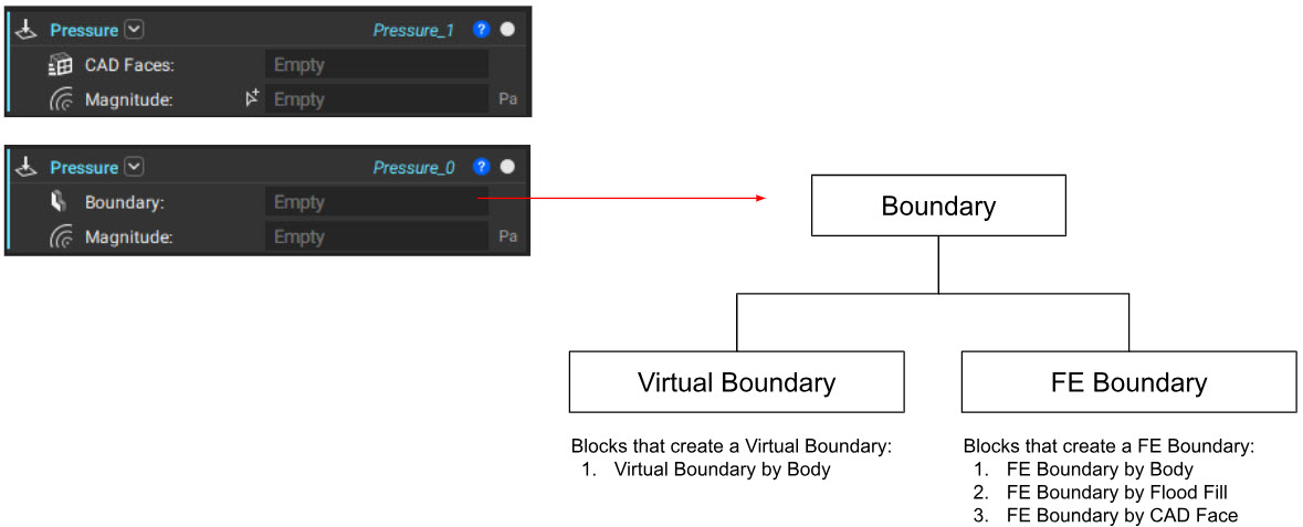
If your model includes a set of CAD Faces that correctly denotes the location of the boundary condition, use the first overload, whether the domain is an FE Domain or Virtual Domain.
If a CAD Face is unavailable, use the second overload that accepts the Boundary base type. If the domain is an FE Domain, use the FE Boundary by Body block to scope the location of the boundary condition. These blocks have been available for many releases and are hopefully familiar.
Use the Virtual Boundary by Body block to define the boundary condition's location for a Virtual Domain. This block functions like the FE Boundary by Body; however, the entities are selected when the analysis runs. There is no visual feedback before the analysis block runs, so you’ll need to verify the boundary location after completing the analysis.
The Virtual Boundary by Body can also be used with an FE Domain. Identifying mesh entities for boundary conditions, but when the analysis begins. This enables boundary conditions to be set once and reused across multiple meshes, making it especially useful for applying the same conditions to multiple FE models. For example, boundary conditions from Topology Optimization can be reused in a downstream Static Analysis of the final design.
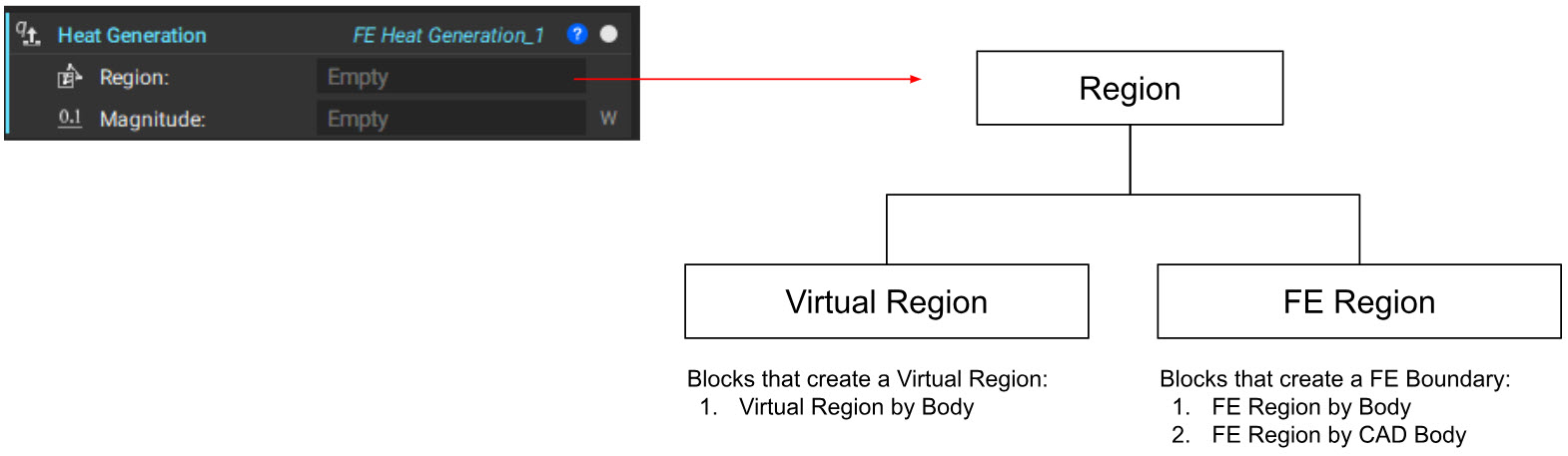
A similar pattern exists for scoping body forces to regions. A Region base type has been introduced, the parent class for either an FE Region or Virtual Region. An FE Region can be created by FE Region by Body and FE Region by CAD Body blocks. In contrast, a Virtual Region is constructed with the Virtual Region by Body block.
Before nTop 5.23, the Boundary by Body block was used to reuse boundary conditions on multiple FE Models. This block has now been deprecated in favor of the Virtual Boundary by Body. In doing so, the selection of mesh entities (Nodes, Edges, and Faces) has been eliminated. nTop will automatically apply the boundary conditions to the appropriate mesh entity depending on the boundary condition type. The following table denotes the mesh entity used for each boundary condition when using the Virtual Boundary by Body or Virtual Regions by Body.
| Boundary Condition: | Operating on the following mesh entities: |
| Acceleration Load | cells |
| Bearing Force | faces |
| Center of Mass Response | cells |
| CFD Boundary on FE Mesh (BETA) | nodes |
| Convection Boundary Load | faces |
| Cyclic Symmetry (BETA) | nodes |
| Cylindrical Restraint | nodes |
| Demold Constraint | cells |
| Displacement Response | nodes |
| Displacement Restraint | nodes |
| Edge Force | edges |
| Export FE Mesh [Boundary] | nodes |
| Export FE Mesh [Region] | cells |
| Export FE Model [Boundary] | nodes |
| Export FE Model [Region] | cells |
| FE Beam Attribute | beams |
| FE Shell Attribute | shells |
| FE Solid Attribute | cells |
| Force | faces |
| Heat Generation | cells |
| Mass Response | cells |
| Max Feature Size Constraint | cells |
| Moment of Inertia Response | cells |
| Overhang Constraint | faces |
| Passive Region Constraint | cells |
| Point Force | nodes |
| Point Moment | nodes |
| Point Restraint | nodes |
| Pressure | faces |
| Radiation Boundary Load | faces |
| Reaction Force Response | nodes |
| Remap Constraint | cells |
| Rigid Connector (BETA) | nodes |
| Rotational Force | cells |
| Stress Response | cells |
| Structural Bonded Contact | nodes |
| Structural Compliance Response | cells |
| Surface Force | faces |
| Surface Heat Flux | faces |
| Temperature Restraint | nodes |
| Thermal Bonded Contact | nodes |
| Tie Constraint | nodes |
| Volume Fraction Response | faces |
| Volumetric Heat Generation | faces |
5.0 Changes to FE Point
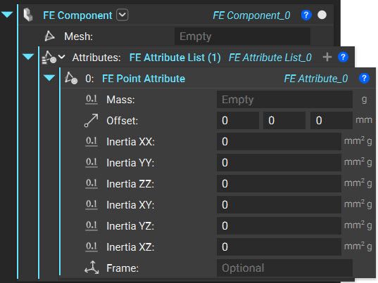
The method for creating and using point mass components in nTop has been updated to enable future features. The current approach for using a point mass and the new version are outlined below:
| Before nTop 5.23 | nTop 5.23 |
 |
|
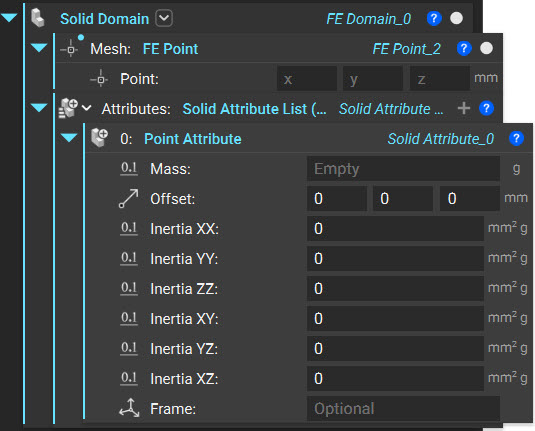
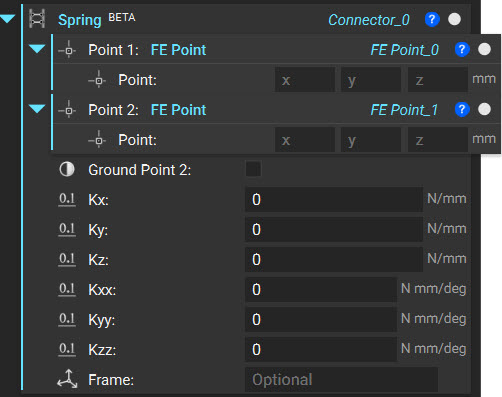
Similar to using an FE Mesh to prescribe a component/domain, we are now introducing the concept of an FE Point. The FE point creates a six-degree of freedom node that can be included in a simulation analysis and used as more than a point mass. The FE Point can be used as a boundary or region to apply acceleration loads and heat flux BCs. The new behavior of the FE Point mimics an FE Mesh. However, it only contains one node and six possible degrees of freedom.
Previously generated workflows and files will automatically update when opened in nTop 5.23, and the results will remain constant. The point itself will become a variable and be used in any/all current locations of the previous point component.
6.0. New blocks and types for CFD
With nTop 5.23 comes support for Computational Fluid Dynamics (CFD). With that five new blocks and two types have been added to aid the setup of isothermal fluid flow problems. As more CFD features are added, additional blocks will be released.
| Block Name: Air | |
| Location: | Fluids [Beta] |
| Description: | General Purpose Air at NIST (293.15K, 100KPa) |
| Output: | Isotropic Material |
| Block Name: Flow Analysis | |
| Location: | Fluids [Beta] |
| Description: |
Calculates the pressure and velocity on a Virtual Model. The solution uses a Lattice Boltzmann Method. A transient simulation is initiated and continues until the flow reaches a statistically steady state, returning time-averaged pressure and velocity fields. This block requires an NVIDIA GPU. |
| Input 1: | The Virtual Model represents the fluid domains to be simulated. |
| Input 2: | The Boundary Conditions are to be used for the analysis. At least one Pressure and one Velocity Boundary condition are required. |
| Input 3: | The size of the cells used in the analysis. |
| Output: | CFD Analysis Result |
| Block Name: Fluid Attribute | |
| Location: | Fluids [Beta] |
| Description: | Define material properties as attributes of a fluid. |
| Input 1: | The underlying material. |
| Output: | Fluid Attribute |
| Block Name: Isotropic Fluid Property | |
| Location: | Fluids [Beta] |
| Description: | Defines an Isotropic Fluid Property. |
| Input 1: | Kinematic viscosity. |
| Output: | Isotropic Fluid Property (Converts to Isotropic Material Property) |
| Block Name: Velocity [Boundary] | |
| Location: | Fluids [Beta] |
| Description: | A boundary condition that specifies a fluid’s velocity entering or leaving a Domain. |
| Input 1: | The Boundary selected for constant velocity. |
| Input 2: | The velocity vector. |
| Input 3: | The reference frame for the components of the Vector. If a Frame is not specified, the components are in the global coordinate system. |
| Output: | Velocity (Converts to Boundary Condition) |
| Block Name: Velocity [CAD Face List] | |
| Location: | Fluids [Beta] |
| Description: | A boundary condition that specifies a fluid’s velocity entering or leaving a Domain. |
| Input 1: | The Boundary selected for constant velocity. |
| Input 2: | The velocity vector. |
| Input 3: | The reference frame for the components of the Vector. If a Frame is not specified, the components are in the global coordinate system. |
| Output: | Velocity (Converts to Boundary Condition) |
| Block Name: Water | |
| Location: | Fluids [Beta] |
| Description: | General Purpose Water at NIST (293.15K, 100KPa). |
Note: The existing Pressure block can now be used in a structural or fluid flow simulation.
7.0. How to update blocks that did not automatically update
a. Replace Boundary by Body with Virtual Boundary by Body
b. Replace Region by Body with Virtual Region by Body
8.0. Recovery results from previous versions
a. No results should change
9.0. What's Next
nTop 5.23 introduces the first native CFD solution in nTop, representing a significant advancement in simulation capabilities that can be used in your computational models. This initial release focuses on isothermal internal flow simulations, establishing a foundation for future enhancements.
Future updates will expand CFD functionality with several key features:
- Conjugate Heat Transfer (CHT): The ability to solve heat transfer between solids and fluids, enabling accurate simulations for applications such as heat exchangers and turbine blades.
- External Aerodynamics: Support for compressible flow and adaptive grid refinement, facilitating the analysis of high-speed external flows, aerodynamic forces, and drag characteristics.
- Turbomachinery Applications: Enhanced capabilities for moving boundaries and rotating components, essential for high-fidelity simulations of fans, pumps, turbines, and other rotating machinery.
These forthcoming features will further advance fluid dynamics simulation within nTop, enabling rapid design and analysis of increasingly complex engineering challenges.
Appendix: Summary of block and type changes
Renamed Blocks
| Old Block Name | New Block Name |
| Boundary by Body | Virtual Boundary by Body |
| FE Component (Mesh) | Solid Domain |
| FE Face Boundary | FE Boundary by CAD Face |
| FE Lattice Component | FE Lattice Domain |
| FE Model | Simulation Model |
| FE Solid Attribute | Solid Attribute |
| FE Solid Component | FE Solid Domain |
| Parametric FE Component | Parametric FE Domain |
| Parametric Lattice Component | Parametric Lattice Domain |
| Parametric Shell Component | Parametric Shell Domain |
| Parametric Shell-Infill Component | Parametric Shell-Infill Domain |
| Parametric Voronoi Component | Parametric Voronoi Domain |
| Region by Body | Virtual Region by Body |
Renamed Types
| Old Type Name | New Type Name |
| FE Attribute | Solid Attribute |
| FE Body Force | Body Force |
| FE Boundary Force | Boundary Force |
| FE Connector | Connector |
| FE Convection Heat Flux | Convection Heat Flux |
| FE Cylindrical Restraint | Cylindrical Restraint |
| FE Force | Force |
| FE Heat Flux | Heat Flux |
| FE Heat Generation | Heat Generation |
| FE Model Load | Model Load |
| FE Pressure | Pressure |
| FE Radiation Heat Flux | Radiation Heat Flux |
| FE Remote Force | Remote Force |
| FE Remote Restraint | Remote Restraint |
| FE Restraint | Restraint |
| FE Temperature Restraint | Temperature Restraint |
| Parametric FE Component | Parametric FE Domain |
New Blocks
| Block Name | Block Description |
| FE Point | Creates a six degree of freedom node that can be included in a simulation or optimization. |
| Flow Analysis |
Calculates the pressure and velocity on a Virtual Model. The solution uses a Lattice Boltzmann Method. A transient simulation is initiated and continues until the flow reaches a statistically steady state, at which point it returns time-averaged pressure and velocity fields. This block requires an NVIDIA GPU. |
| Fluid Attribute | Define material properties as attributes of a fluid. |
| Fluid Domain | Create a Fluid Domain by assigning a Fluid Attribute to an Implicit Body. |
| Isotropic Fluid Property | Defines an Isotropic Fluid Property. |
| Solid Domain (Implicit Body overload) | Creates a Solid Domain by assigning Solid Attributes to an Implicit Body. |
| Simulation Model (Virtual Domain overload) | Combines a list of Virtual Domains and corresponding Connectors into a Virtual Model. |
| Velocity (Boundary Overload) | A boundary condition that specifies a fluid’s velocity entering or leaving a Domain. |
| Velocity (CAD Face List Overload) | A boundary condition that specifies a fluid’s velocity entering or leaving a Domain. |
New Types
| Type Name | Type Description |
| Boundary | The location of a boundary condition on a Domain. |
| FE Point | A six degree-of-freedom node that can be included in a simulation analysis. |
| Fluid Attribute | An object with material assignment and fluid properties of selected interior regions (or the entirety) of a fluid domain. |
| Isotropic Fluid Property | Properties for an isotropic fluid. |
| Region | A select region of a Domain. |
| Velocity | A boundary condition that specifies a fluid’s velocity entering or leaving a domain. |
| Virtual Boundary | An object that defines the location of a boundary condition on a Domain before meshing. |
| Virtual Model | An object with information about all the Virtual Domains and the connectivity information between them. |
| Virtual Domain | An object with information about a Virtual Domain with corresponding attributes assigned to it. |
| Virtual Region | An object that defines a region of a Domain before meshing. |
Updated Blocks
| Deprecated Block | Replaced by Block |
| Boundary by Body | Virtual Boundary by Body* |
| FE Component (Point Overload) | FE Point + Solid Domain |
| Region by Body | Virtual Region by Body* |
* These blocks will not have an Update button to update the block automatically. They will have to be manually updated to the latest version.