
nTopology 3.30 is here! This release features Import Part 2.0, which now has new properties for CAD Assemblies imported from your native CAD program, allowing you to identify which part chips you need since they have the same CAD names. The Custom Unit Cell (Beta) block creates a unit cell from a graph lattice that consists of beams, faces, or a combination of both. Lastly, you can quickly identify the location of minimum and maximum values in simulation results by selecting the “Min/Max” icon in the HUD and add persistent probes. Please visit support.ntopology.com to gain access to helpful tutorials and support articles.
Import Part 2.0: CAD Assembly Support
Custom Unit Cell (Beta)
Graph from Line Segments
Min & Max HUD Tags & Persistent Probes
Usage Improvements
Bug Fixes
Import Part 2.0: CAD Assembly Support
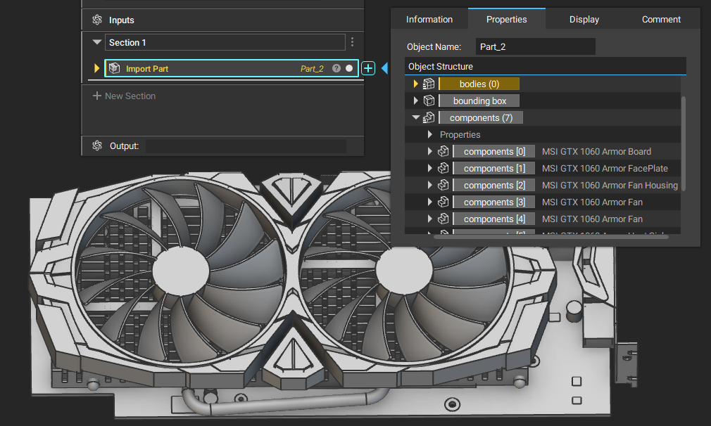
- CAD assemblies are no longer flattened with our latest version of the Import Part block.
- To preserve the assembly hierarchy on import, we added a new type called Component that you will find under any Part objects.
| CATProduct imported through Import Part 2.0 in nTopology 3.30 | CATProduct imported through Import Part 1.2 in nTopology 3.30 |
|
Assembly hierarchy is found as a list of components |
Assemblies will be flattened as a list of bodies |
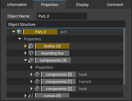
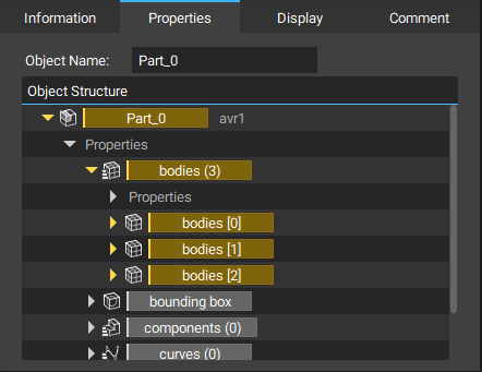
- Component contains instance, placement, and template.
- Instance is a Part type object representing the CAD component in the assembly structure. You will find all bodies and curves of each assembly component under this.
- Placement is a Transform object required for transforming the Template into the Instance.
- Template is a Part type object representing the original part level design.
- You can apply the design workflow to the Template and transform with Placement to locate the nTopology design and the rest of the components in the assembly.
- Bodies and curves are now sorted by bounding box Xmin < Ymin < Zmin < Xmax < Ymax < Zmax. (i.e. the geometry with the least Xmin is first). Faces aren't sorted based on the geometry.
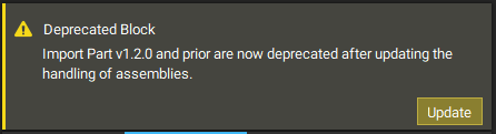
- Updating old blocks to the new version via the Update button in the Deprecated Block warning will not correctly update references. References must be updated manually.
Custom Unit Cell (Beta)
- We renamed the Custom Implicit Unit Cell block to Custom Unit Cell. In addition to implicit Unit Cells, the block now has a second overload that you can use to create custom cells from a Graph. The output is a 1 Parameter Unit Cell, with thickness being the parameter. You can input this Unit Cell and your thickness value into the Periodic Lattice block.
- The overload accepts a Graph as input and a Bounding Box to define the cell’s domain. To construct the Graph that defines your custom cell, you can use the new utility block Graph from Line Segments.
- The input Graph can consist of beams, faces, or a combination of both. The geometry can be 2D or 3D. When creating 2D Unit Cells, remember that the input Domain must be a 3D Bounding Box.
- If you have a CAD file containing line segments that you’d like to convert into a custom cell, use the Import Part block to import your file. Drag out the curves property chip, and use the Line Segment block to construct lines using each degree 1 curve’s endpoints. Once you have a list of line segments, you can make a Graph using Graph from Line Segments and then input that into the Custom Unit Cell block.
- Block Name: Custom Unit Cell
- Location: Lattices > Unit Cells
- 2nd Overload (Beta):
- Description: Constructs a 1 Parameter Unit Cell from a Graph. Parameter 1: Thickness.
- Input 1: Graph - Graph from which to construct the custom Unit Cell.
- Input 2: Domain - Bounding Box to define the domain of the custom Unit Cell.
- Output: 1 Parameter Unit Cell
A custom 1 Parameter Unit Cell constructed using Graph from Line Segments used to make a lattice in the Periodic Lattice block:
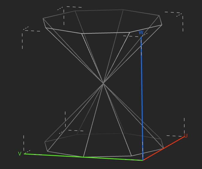
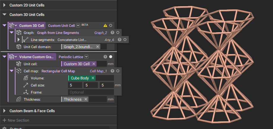
Graph from Line Segments
- We released a new lattice utility block Graph from Line Segments. You can use this block in a variety of different scenarios:
- Custom Unit Cell creation: Graph from Line Segments can be used as the input to Custom Unit Cell to construct your own 2D or 3D unit cells.
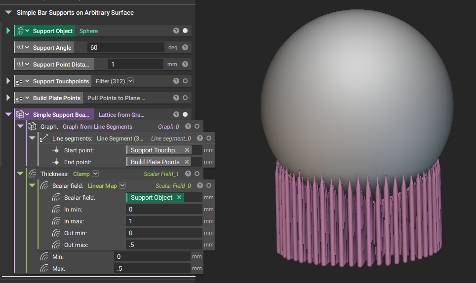
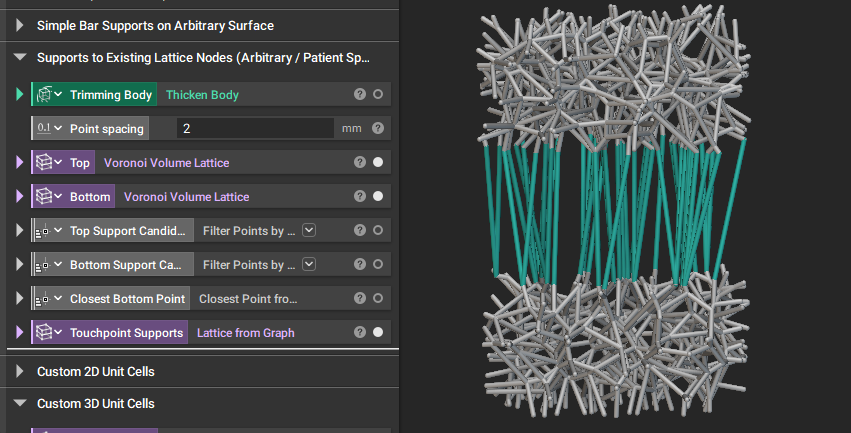
- Support generation: you can create a support structure by first creating touch points on your model and target points on your build plate. Use these as the start and end points in the Graph from Line Segments block.
Simple support points on a volume:
Supports between two lattices’ nodes:
Min & Max HUD Tags & Persistent Probes
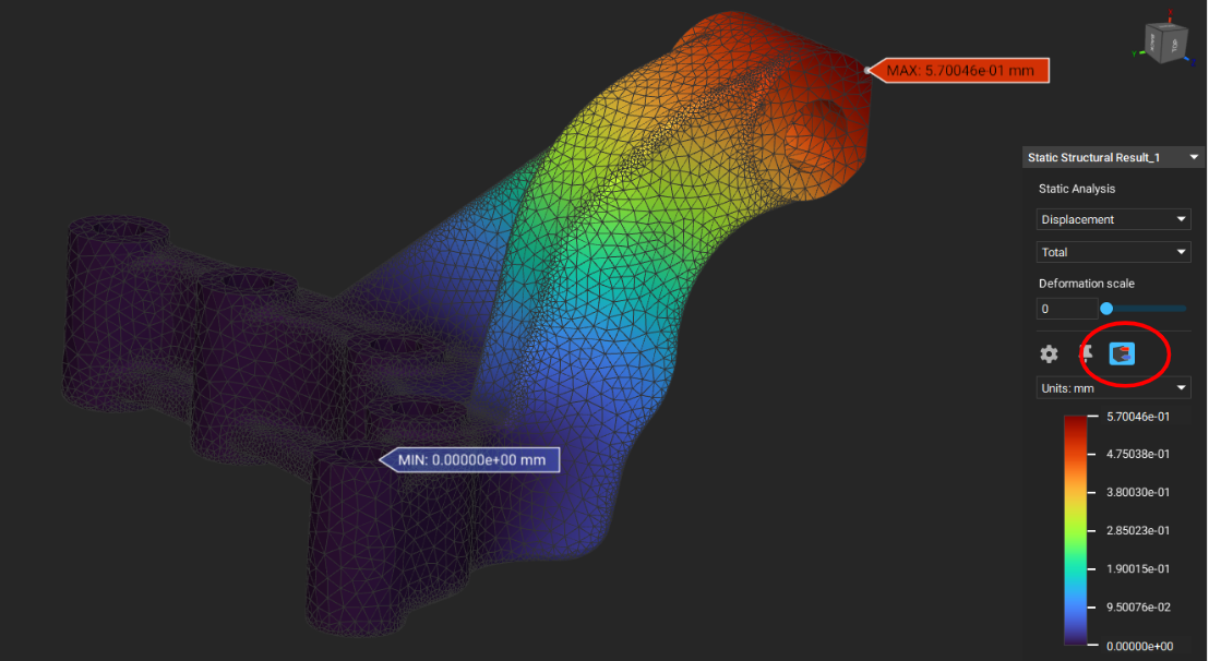
- When visibility is toggled on for any simulation analysis blocks, you can quickly identify the location of minimum and maximum values by selecting the “Min/Max” icon in the HUD. The location of the minimum value will be automatically identified with a blue tag, while the maximum value will be identified with a red tag.
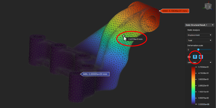
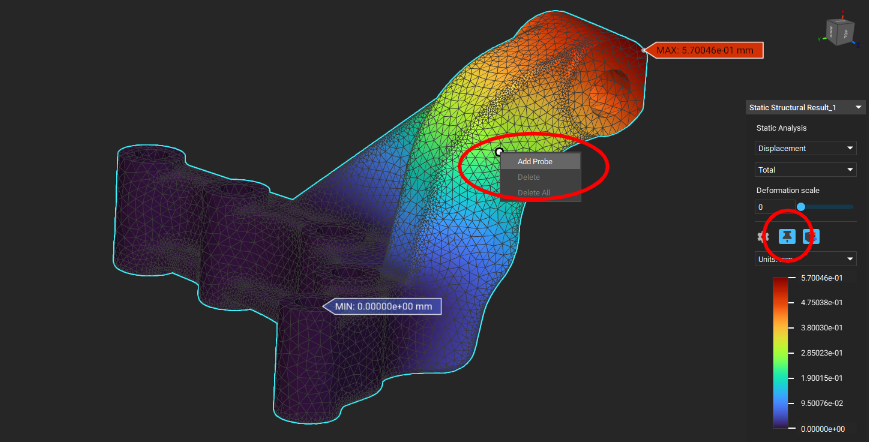
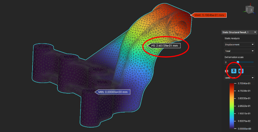
- Probing simulation results has also been extended in this release. Probing is enabled by selecting “Probe Mode” in the HUD. In Probe Mode, hovering over mesh vertices will reveal the simulation result at that location. You can create a persistent probe by clicking on a vertex and selecting “Add Probe” from the context menu. To remove a probe, click on the probe and select “Delete” from the context menu. Selecting “Delete All” from the context menu will remove all probes.
Minimum and maximum results are identified by selecting the “Min/Max” icon above the HUD legend.
Select the “Probe Mode” icon about the HUD legend to interactively probe results at mesh vertices.
Right mouse click and select “Add Probe” to create a persistent probe at the desired location.
Persistent probe with value.
Usage Improvements
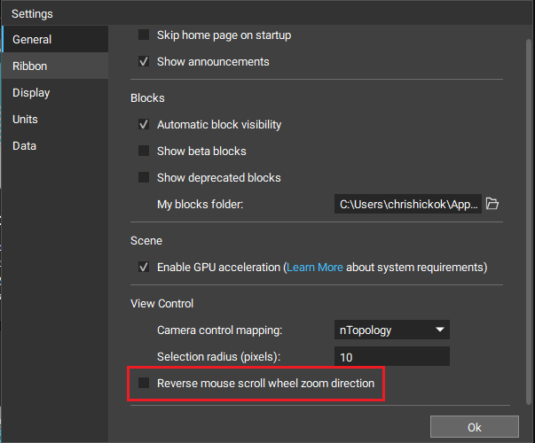
- We have added an option under Settings to reverse the scroll wheel zoom direction.
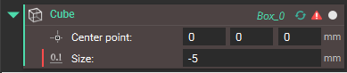
- Blocks with errors now display a red indicator on the left side of the input with the error to help you more quickly troubleshoot
.
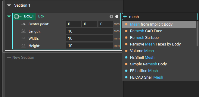
- Context Search now works for variable and non-variable blocks to help you discover and place compatible blocks more efficiently.
Bug Fixes
- We fixed an issue with hover-activated tooltips not showing when there were active windows open (e.g. Imported Blocks menu) within nTopology.
- We fixed an issue where embedding blocks with open information panel would not display correctly until the panel is closed and reopened.
- We fixed an issue causing nTopology to sometimes unexpectedly exit when checking for Custom Blocks in the MyBlocks folder.
- We fixed an issue where copying and pasting an “Equals” block would also paste the references of the “Equals” block.
- We fixed an issue with not being able to read Topology Optimization results saved in 3.28 with the 3.29 release. 3.30 can now open files created with 3.28.
- We fixed an issue causing the heatflux values to be computed incorrectly for shell elements in the Thermal Analysis block. Please rebuild your Thermal Analysis block if it contains shell elements.
- We fixed an issue that created an inaccurate slice stack from an Implicit Body that was smoothened using the Smoothen Body block.
- We fixed an issue causing nTop to unexpectedly exit when running the CAD Body from Implicit Body (Beta) block with models containing thin features or ribs.