Objective:
Learn how to use Natural Frequency Response in topology optimization.
Method 1: Maximising the Natural Frequency Response
Method 2: Constraining the Natural Frequency Response
Applies to:
- Topology Optimization
Procedure:
What is Topology Optimization?
It is a process that performs a numerical design operation that determines the optimal shape of a part within the bounds of a Design Space based on a set of objectives and constraints. The block allows the user to design geometries that best achieve the desired objective(s) while considering complex and multivariate loading conditions and design constraints. nTop’s TopOpt algorithm uses the Solid Isotropic Material with Penalization (SIMP).
This article uses Simulation/Optimization and both of them in nTop have two requirements: FE Mesh and Boundary Conditions (BCs). Follow the instructions in the links below to prepare your model for simulation.
FE Mesh
Boundary Conditions (BCs)
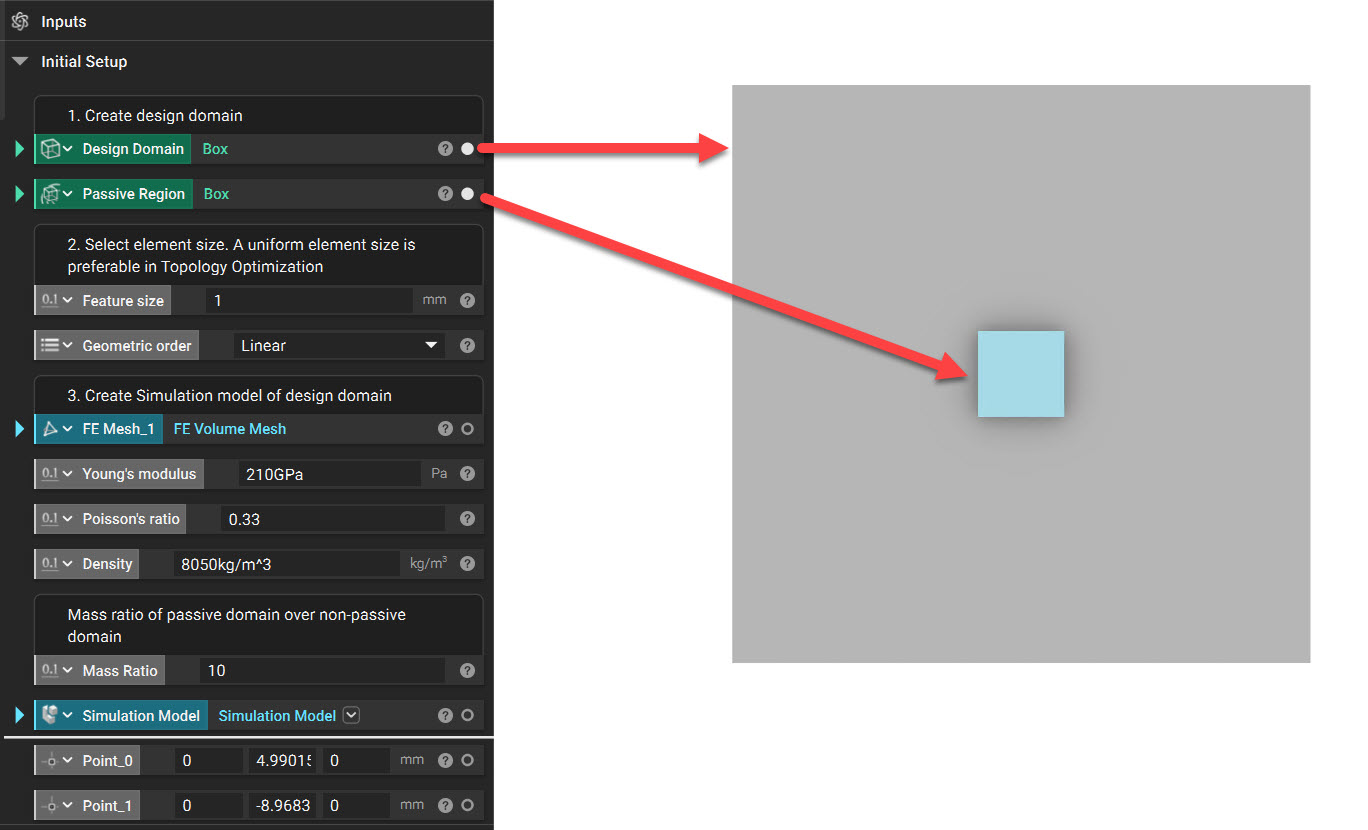
1. Set up the Design Domain and any Passive Region. In this example, we use a thin square plate with a box region as a Passive Region.
2. As mentioned above, we must mesh the Design space and prepare our Simulation Model. We must apply Displacement Restraint on the Top, Bottom, and Sides.
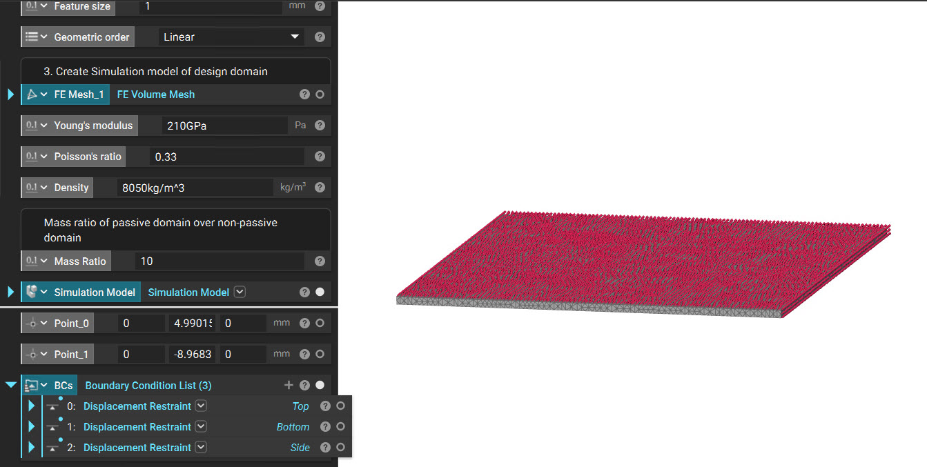
3. We run a Modal analysis to ensure loads and the design space mesh have been set up correctly and that no rigid body modes exist. If you have any questions about the setup, this article can help you (How can I set up a simulation?). In this example, we run the Modal Analysis for five modes.
The values we obtained from the Modal Analysis are:
| Mode | Eigenfrequencies |
| 1 | 21774.32645 |
| 2 | 21780.52417 |
| 3 | 33828.68546 |
| 4 | 43760.28749 |
| 5 | 44350.11626 |
We are going to see two methods below, which maximize the frequency response and contain the frequency within a range.
Method 1: Maximizing the Natural Frequency Response
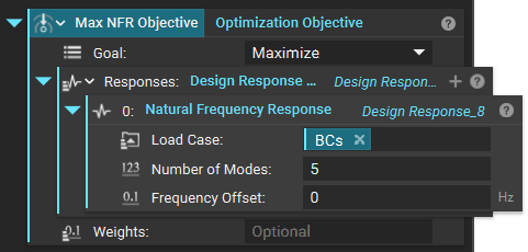
1. We add an Optimization Objective and set the following parameters.
- Goal: Maximize
- Design Response List
- Natural Frequency Response
- Load Case: Boundary Conditions from the above step
- Number of Modes: 5
- Frequency Offset: 0 Hz
- Natural Frequency Response
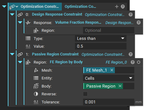
2. We now add an Optimization Constraints List. This would have a Design Response Constraint and a Passive Region Constraint. Our goal in this optimization is to maximize the natural frequency response while reducing the volume by 50%.
3. We now run the Topology Optimization block with the Model, Constraint, and Objectives we created in the above steps.
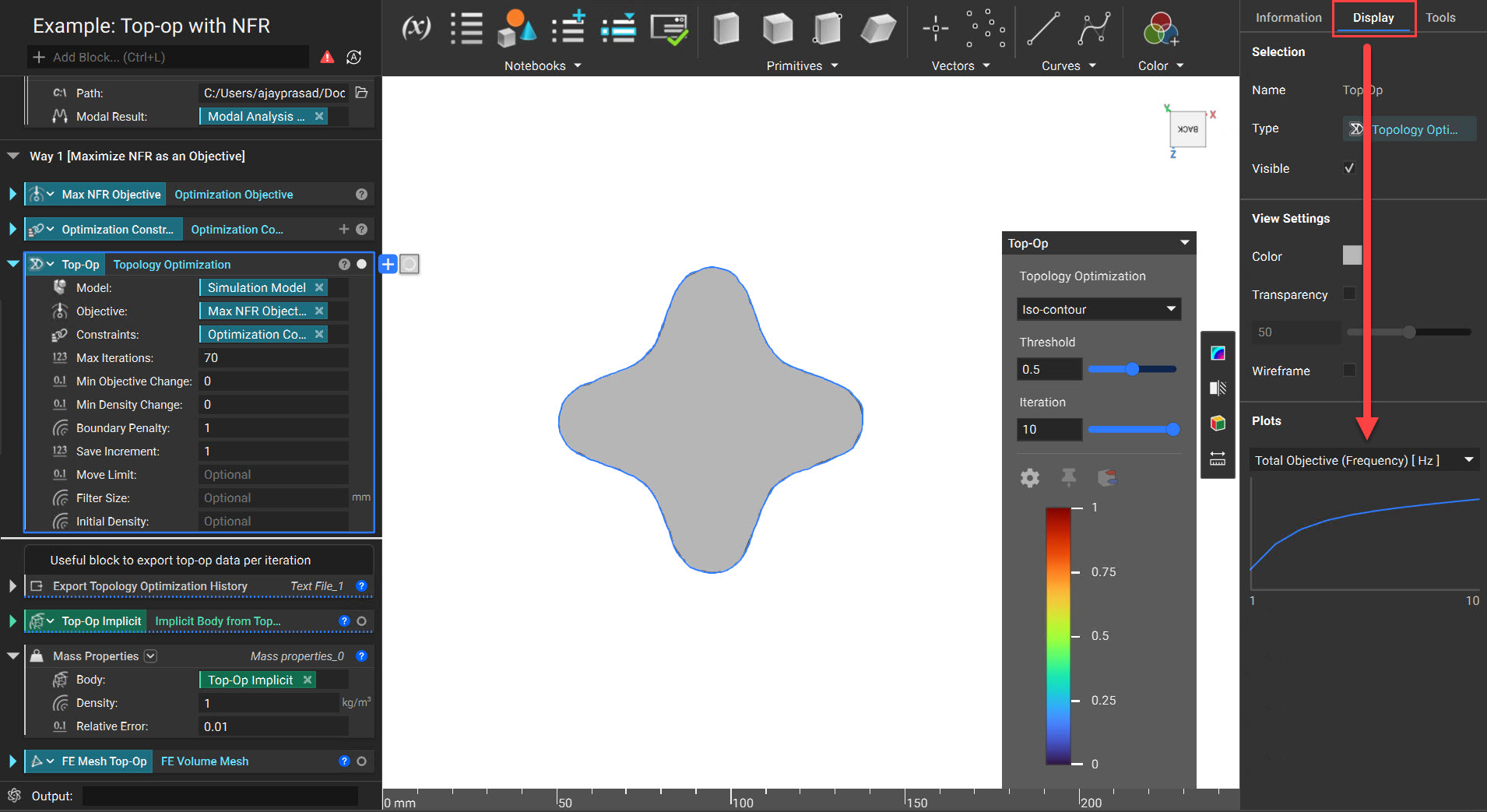
While the Topology Optimization is iterating, you can check how the constraints are met in each iteration by opening the Right Side Panel and clicking on the Display tab. You can export this history for each iteration using the Export Topology Optimization History block.
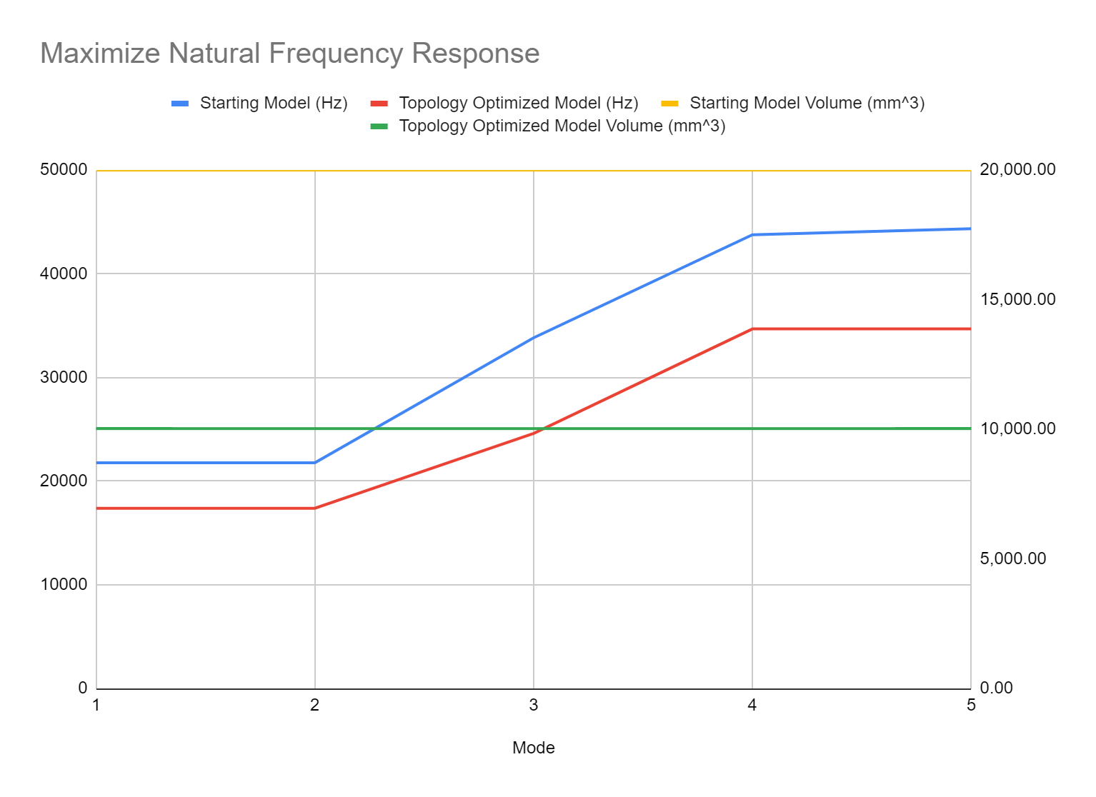
4. Check the results obtained by meshing and performing Modal Analysis as we did in the first section of this article.
Method 2: Constraining the Natural Frequency Response
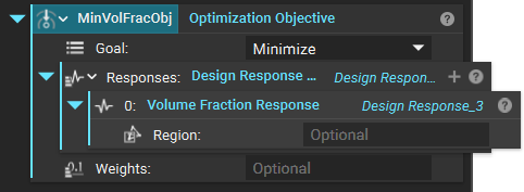
1. We add an Optimization Objective and set the following parameters to minimize the natural frequency response.
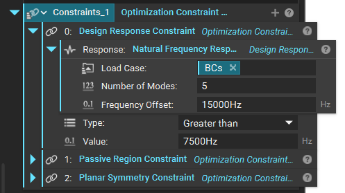
2. We now add an Optimization Constraints List. This would have a Design Response Constraint, Planar Symmetry Constraint, and a Passive Region Constraint. In this example, We are trying to avoid any modes from 7500Hz (Lower Bound) to 22500Hz (Upper Bound)
- Frequency offset = 0.5*(Upper + Lower) = 15000 Hz for input in the Natural Frequency Response block.
- Greater than value = 0.5*(Upper - Lower) = 7500 Hz for input in the Design Response Constraint block.
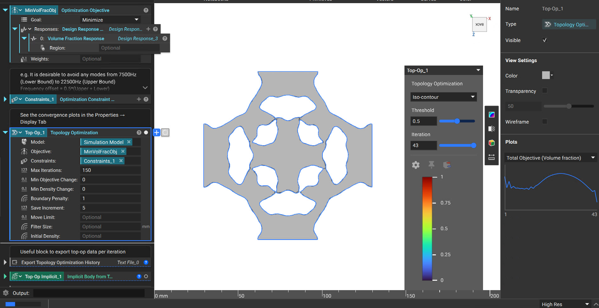
3. We now run the Topology Optimization block with the above parameters.
4. Check the results obtained by meshing and performing Modal Analysis as we did in the first section of this article.
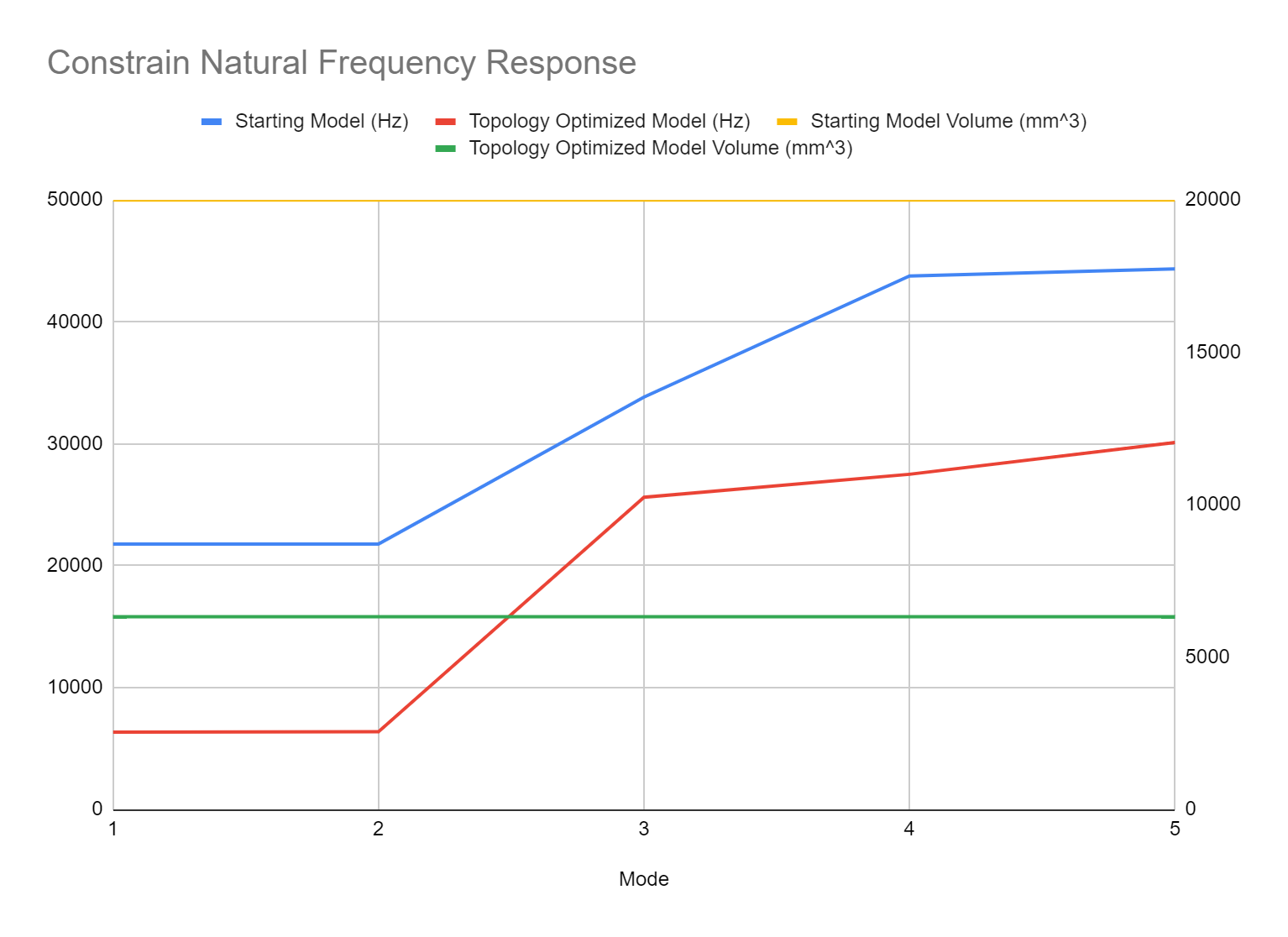
We can verify that there are no frequencies in the 7500Hz to 22500Hz Band.
| Mode | Eigenfrequencies |
| 1 | 6350.851816 |
| 2 | 6386.349747 |
| 3 | 25619.41088 |
| 4 | 27501.22537 |
| 5 | 30108.87244 |
And that's it. You have successfully applied Natural Frequency Response in your Topology Optimization.