Objective:
Learn what a Simulation Model is and how to create one.
What is a Simulation Model?
A Simulation Model brings together all of the necessary elements for the part to be analyzed, whether in simulation, optimization, or further analysis. A Simulation Model is built up of Domains and Connectors. There are several different types of domains depending on the type of simulation being performed. Most domains contain an input body type and Attributes, while the Lattice Domain only requires a Material instead of an Attribute. Connectors are made up of Tie Constraints, Structural Bonded Contacts, or Thermal Bonded Contacts that allow the analysis of multiple domains. A Simulation Model does not need a connector to run if it only has one FE Mesh. If it has multiple domains, there will always be one less connector compared to the total number of domains.
| Model: | Domain Type: | Body Input: | Attribute: |
| Simulation Model | Lattice Domain | Lattice | N/A |
| Lattice Domain | Lattice Mesh | N/A | |
| Fluid Domain | Implicit Body | Fluid Attribute | |
| Solid Domain | FE Mesh | Beam/Point/Shell/Solid Attribute |
Procedure:
1. Define a Material: The Simulation Model needs a Material block to assign properties to the part. nTop has some preset common materials available, or you can build your own Isotropic or Orthotropic Material.
- Add the Isotropic Material block.
- Add an Isotropic Material Property by double-clicking in the Property input.
- Add the Isotropic Linear Elastic Property and enter the following values:
- Young's modulus: 2.21e+13 Pa
- Poisson's ratio: 0.3
2. Add a Solid Domain and Material Attributes: This step assigns the material properties to the mesh. Attributes define the material, thickness, frame, and region in which it occurs. Three types of Attributes can be chosen: Solid, Beam, and Shell. Each type allows for the selection of different elements.
- Add a Solid Domain block and insert your FE Mesh into the Mesh input (from this tutorial).
- Double-click in the Attributes input and add a Solid Attribute.
- Drag the Material from the last step into the Material input.
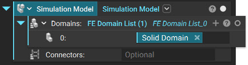
3. Create a Simulation Model: The last step is to add a Simulation Model block. In this example, we are using only one domain, so we don't need to expand the Domain list. Drag and insert the Solid Domain from the last step into the Domain input. For this example, we will be leaving the Connectors empty.
And that’s it! You’ve successfully created a Simulation Model.
Are you still having issues? Contact the support team, and we’ll be happy to help!
You can move on to the next article in this series and learn how to select regions of an FE Mesh.
Download the Example file:
- How to Create an FE Mesh
- How can I create a Surface Mesh?
- How to Select Boundaries of an FE Mesh - FE Boundary by Body
- How to Select Boundaries of an FE Mesh - FE Boundary by Flood Fill
- How to use Boundary Conditions
- How to Run a Static Analysis
- How to use Simulation Results to Create a Point Map or Field