Objective:
Learn how to select boundaries using the FE Boundary by Body and Virtual Boundary by Body blocks.
Applies to:
- Simulation
- FE Boundary by Body
- Virtual Boundary by Body
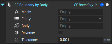
FE Boundary by Body
The FE Boundary by Body block selects entities of an FE Mesh (faces, edges, nodes) within the desired tolerance of an Implicit Body. Depending on the Tolerance, the Implicit Body can be intersected with the mesh or not touching. The Reverse box can be toggled on or off to select the opposite of what was selected.
1. Choose and Prepare the Body for Selection: In this example, we want a Force Boundary Condition to act on the brake pedal's head. To choose that area on the mesh, we need to extract the CAD face (select CAD Face and right-click), convert it to an Implicit Body, and Thicken the body. Thickening the body turns the thin implicit face into an object that can be rendered and used to select entities on the mesh.
2. Select Boundary: Once the selection body is prepared, it needs to be intersected with the FE Mesh to choose the boundary. Follow the steps below to do this:
- Add an FE Boundary by Body block.
- Double-click on the Mesh input to add the existing FE Mesh
- Choose 'Nodes' for the Entity
- Insert the Thickened Body from the last step into the Body input
- Tip: The Body input takes in Implicit parts that don't have to be a thickened surface. There are a variety of other methods available to select the part you want. An example of useful blocks, but not limited to:
- Implicit Body from Curve
- Implicit Body from Thick Lattice
- Implicit Body from Mesh
- Tip: The Body input takes in Implicit parts that don't have to be a thickened surface. There are a variety of other methods available to select the part you want. An example of useful blocks, but not limited to:
Virtual Boundary by Body
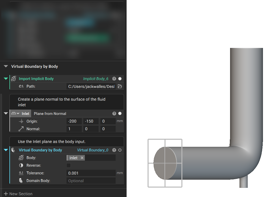
The Virtual Boundary by Body block identifies an Implicit Body to intersect with a Domain to select a boundary. The tolerance applies to checking the boundary of the Implicit Body. The Reverse box can be toggled on or off to select the opposite of what was selected. The Domain Body input is optional and will be used for future capabilities of nTop Fluids.
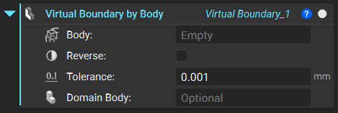
1. Select Boundary: The Virtual Boundary by Body block only requires you to select a body input.
- Add a Plane from Normal block and position it at the center of the intake surface. Ensure the normal direction is directed towards the body.
- Add a Virtual Boundary by Body block. Insert the plane into the Body input.
And that’s it! You’ve successfully selected a boundary using the FE Boundary by Body and Virtual Boundary by Body blocks.
Are you still having issues? Contact the support team, and we’ll be happy to help!
Move on to the next article in this series and learn how to use FE Boundary by Flood Fill.