Objective:
Learn to use the results of a Simulation to drive the design of your part by creating a Point Map or Field.
Procedure:
Under the Simulation tab in the Exchange section, there is a variety of options for using the results of your simulation. You can export the results, meshes, models, and use certain results as point maps to influence your design.
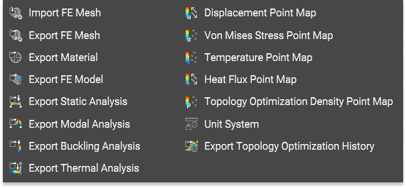
In this example, let's use the Von Mises Stress Point Map.
1. Create a Point Map
-
- Add a Von Mises Stress Point Map
- Insert the Static Analysis block into the input
This creates a Point Map of the Von Mises stress. When visible, you can toggle the Lower or Upper bounds of the Point Map. The Point Map is the stepping stone to utilizing the Simulation results. It can be exported, filtered to show the max or min values and create a Field for further design changes.
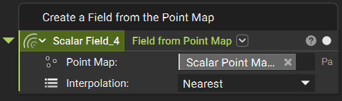
2. Convert the Point Map into a Field
-
- Add a Field from Point Map block
- Insert the Von Mises Point Map into the Point Map input
- Read more about the Extrapolation and Interpolation options here
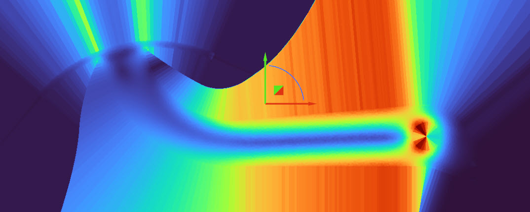
To see the field, use the Field Viewer (hotkey f) to view the field. The field can be used to edit densities, thicknesses, and other values that affect your design.
And that’s it! You’ve successfully created a Field from your static analysis.
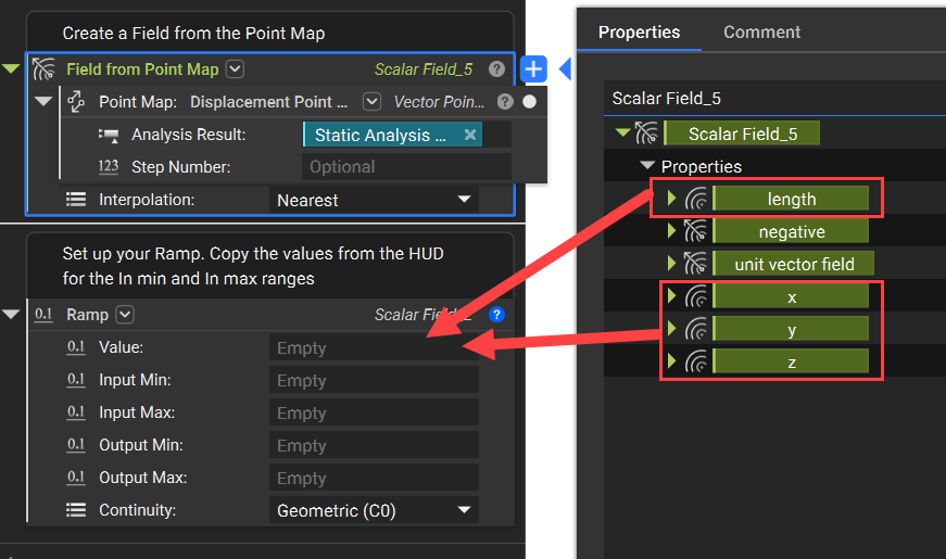
4. If you want to use the Displacement Results:
- Add a Displacement Point Map block
- Insert that into the Point map input on a Field from Point Map block. This creates a Vector Field Point Map because the displacement has a value for each direction (X, Y, Z).
- To use this in a Ramp, open up the Properties of the Field from Point Map block and use one of the Length, X, Y, or Z field chips as the scalar field. The Length field is the resultant Displacement from the Vector fields.
Are you still having issues? Contact the support team, and we’ll be happy to help!