Objective:
Learn how to export FE Data to ANSYS Workbench using different FE data options.
Procedure:
There are different options to choose from while exporting FE data. Based on the requirement, you can choose the most appropriate option.
Block |
Nodes | Elements | Materials | Element Sets | Node Sets | Boundary Conditions | Analysis Settings |
| Export FE Mesh - no sets | 🗸 | 🗸 | |||||
| Export FE Mesh - with sets | 🗸 | 🗸 | 🗸 | ||||
| Export FE Model - no sets | 🗸 | 🗸 | 🗸 | 🗸 | 🗸 | ||
| Export FE Model - with sets | 🗸 | 🗸 | 🗸 | 🗸 | 🗸 | 🗸 | |
| Export Static Analysis | 🗸 | 🗸 | 🗸 | 🗸 | 🗸 | 🗸 |
Exporting FE Mesh with Sets
1. Generate a FE Mesh for the model and Boundary conditions.
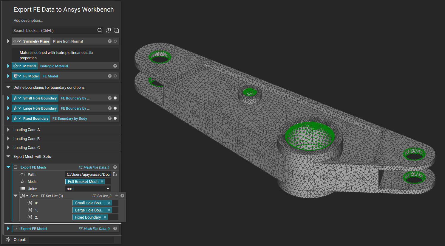
2. Use the Export FE Mesh block.
- Input the Mesh and add the Boundaries in the sets field.
- Update the Path for Mesh Export.
- Select the file type as Ansys Mechanical Input (.cdb)
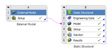
3. Import the exported Ansys Mechanical Input (.cdb) file into Ansys Workbench.
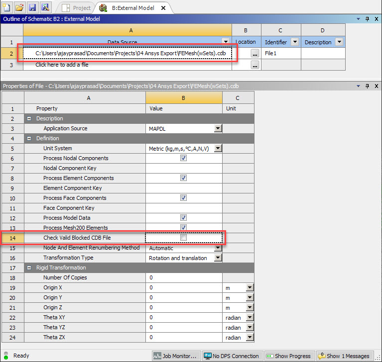
4. Open Setup to modify properties in the Schematic for the External Model
- Select cell 2A to expose the properties pane
- Uncheck “Check Valid Blocked CDB File”
5. Open the Model in Mechanical Model/Static Structural.
- Update it to see the Mesh and Sets are imported as Named Selections. The material for all elements is selected by default when importing a FE Mesh.
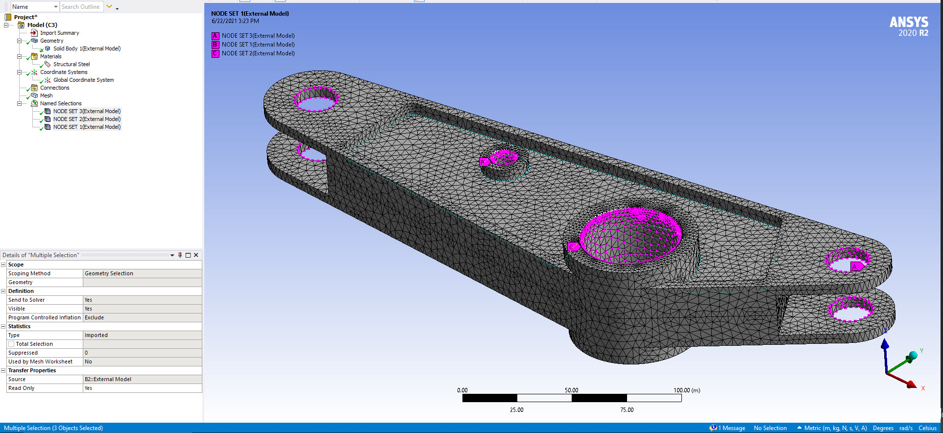
6. Apply Boundary Conditions to the Named Selections using Direct FE in the Environment Ribbon. Note that node sets only support boundary conditions in the Direct FE dropdown. Other boundary conditions are can be applied to geometry which Ansys detects from the mesh.
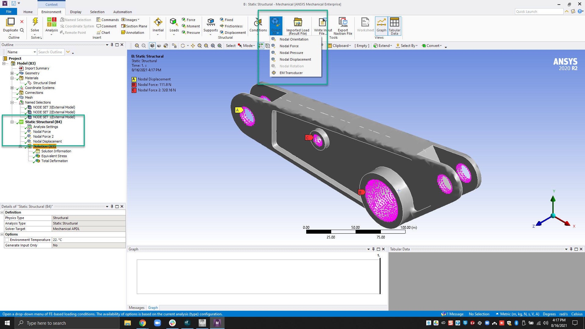
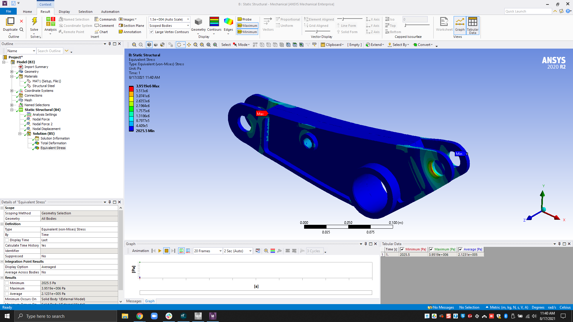
7. Solve the FE Setup and add plots you wish to visualize. See examples of this below: 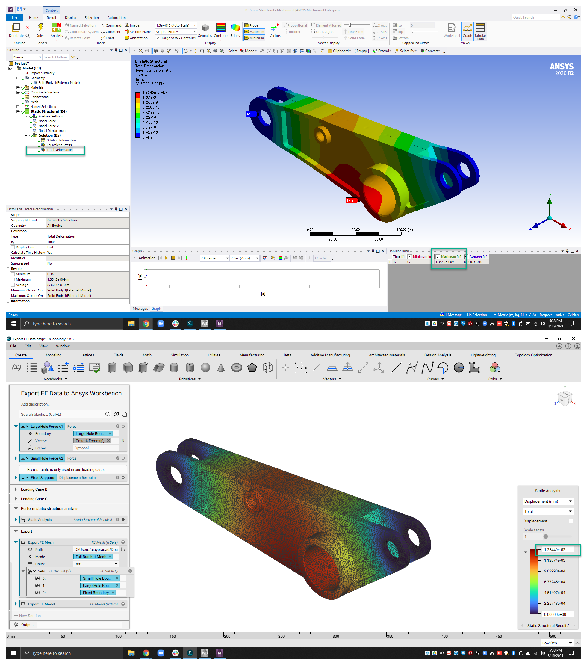
Exporting FE Model with Sets
1. Generate FE Model and Boundary Conditions
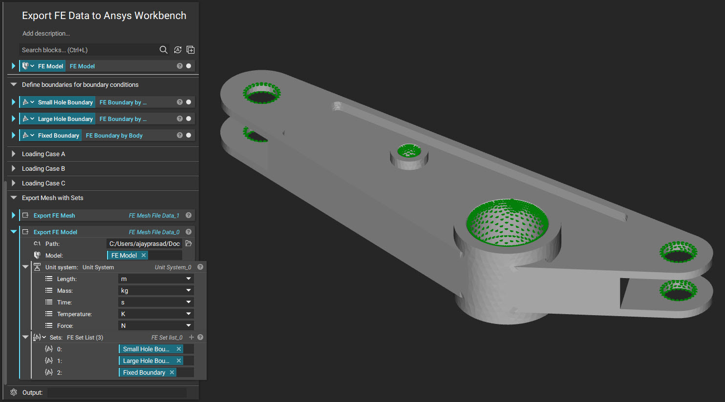
2. Use the Export FE Model block
- Insert the FE Model
- Update the Unit system
- Add the boundaries in sets
- Select the file type as Ansys Mechanical Input (.cdb)
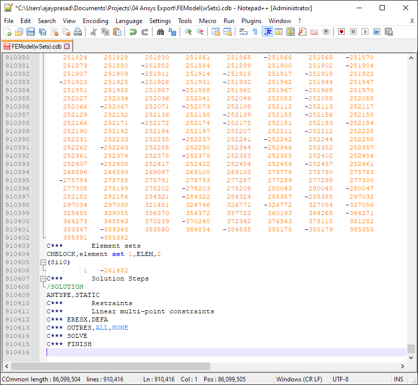
3. Open the exported FE Model (.cdb) file in your preferred code editor.
- Scroll down to the bottom or find "SOLUTION".
- Comment out the last 4 APDL analysis commands by typing C*** before the command.
4. Import the FE Model (.cdb) file into Ansys Workbench.
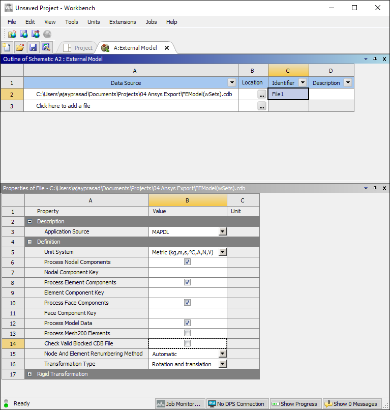
- Double click Setup (this opens up the Outline for the Schematic for the External Model).
- Click Cell "C2" and uncheck the “Check Valid Blocked CDB File”.
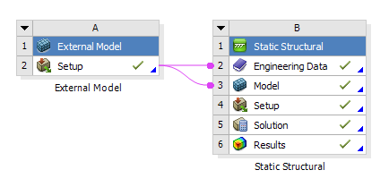
- Connect to Model and Engineering Data cells.
5. Apply Direct FE Loads and Restraints using the Named Sets.
- Refer to Step 7 in the instructions above.
- Solve the Static Structural Analysis on the FE Setup.
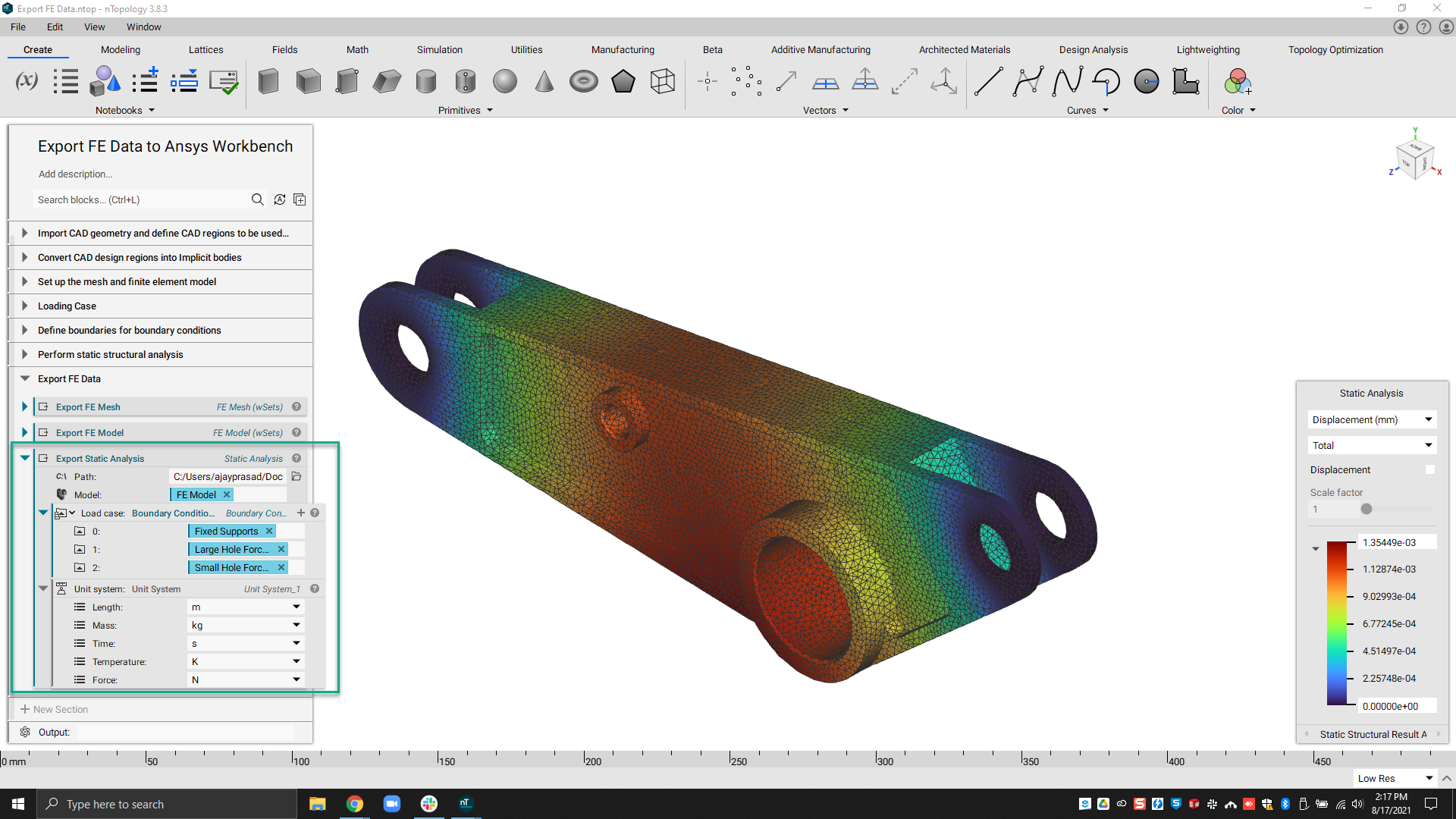
Exporting a Static Analysis
1. Run Static Structural Analysis in nTop. You can find detailed instructions on FE Model Preparation, Generating Boundary Conditions, and applying Loads here How to run a static analysis.
2. Use the Export Static Analysis block.
- Update the input fields with the necessary FE Model, Boundary Conditions, and Unit System.
- Select the file type as Ansys Mechanical Input (.cdb)
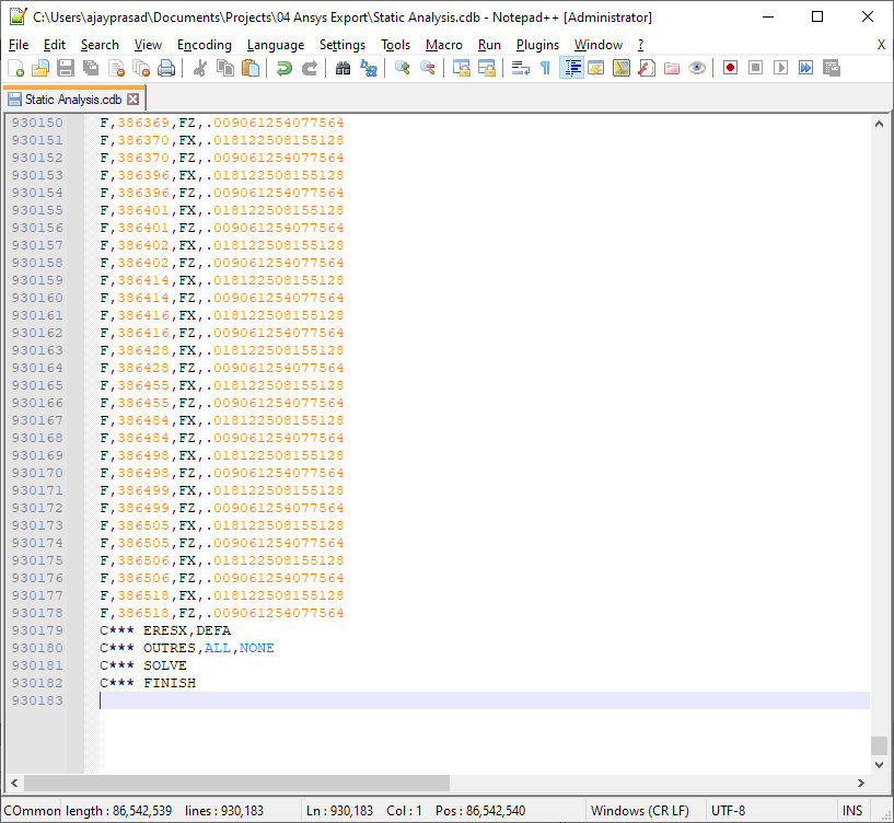
2. Open the exported Static Analyis (.cdb) file in your preferred code editor.
- Scroll down to the bottom or Find "SOLUTION".
- Comment out the last 4 APDL analysis commands by typing C*** before the command.
1. Import the Static Analysis (.cdb) file onto Ansys Workbench.
- Double click Setup (this opens up the Outline for the Schematic for the External Model).
- Click Cell "C2" and uncheck the “Check Valid Blocked CDB File”.
- Connect to Model and Engineering Data cells.
- Check Step 4 in the Export FE Model section for reference.
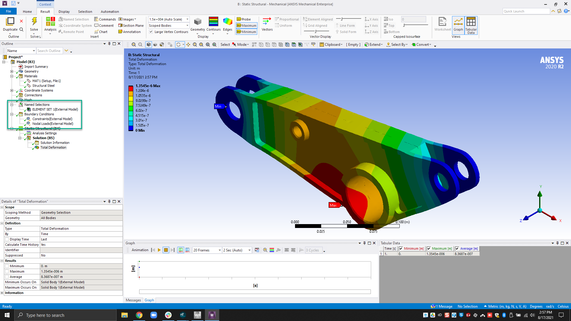
2. Update the Solution in the Static Structural Block to solve the FE Setup.
- Element sets come over in the Named Selection branch.
- There are node sets when importing a Static Analysis, unlike FE Mesh and Model.
- The material model is assigned to the element set.
- Boundary conditions can be viewed in its folder.
And that’s it! You’ve successfully learned to export FE Data to ANSYS Workbench.
Are you still having issues? Contact the support team, and we’ll be happy to help!