Objective:
Convert imported CAD sketches into lattices.
Applies to:
- Graph Lattices
- Custom Graph Unit Cell
Procedure:
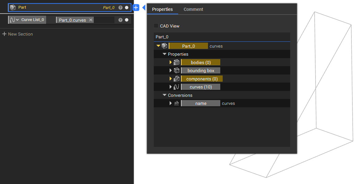
1. Start by importing your CAD sketch
-
- nTop imports all CAD sketches as a 'Curve' type.
Note: If your part only has sketches without models, it may appear blank in the graphic window. To access the curves, open up the properties and drag out the curves property chip.
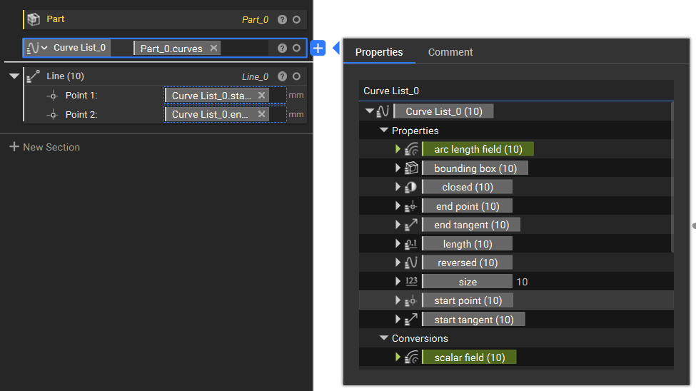
2. Convert the Curves into Line Segments
If you have imported Line Segments but they are imported as a Curve type, you can access the properties and then drag and drop the Start Point and End Point into a Line block.
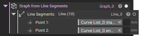
3. Convert Line Segments into a Graph Lattice
Now, we need to convert our line segments into a lattice type. The best method for this is using the Graph from Line Segments block.
Place the result as input for the Custom Unit Cell block.
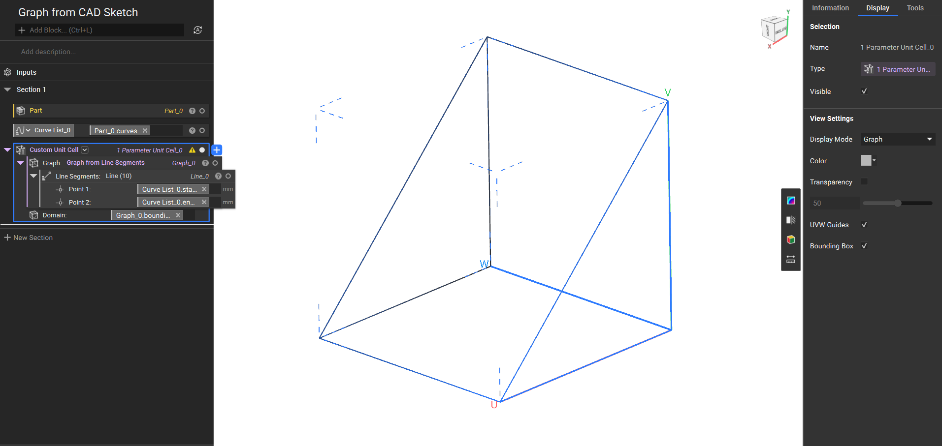
And that’s it! You’ve successfully converted your sketch into a lattice type.
There are several options on what you can do with your lattice. One option is turning the lattice into a Custom Implicit Unit Cell (How to build a custom lattice unit cell).
Are you still having issues? Contact the support team, and we’ll be happy to help!