Overview
This document is a reference for nTop engineers preparing implicit files for slicing in Materialise Magics or the Materialise Build Processor. It covers how to validate your design in nTop before export, and which modeling practices help avoid issues downstream.
The recommended workflow is: design in nTop → validate in the nTop Field Viewer → export → slice in Materialise. Problems caught in the Field Viewer are straightforward to identify and fix. The same problems discovered after slicing can be difficult to trace back to their source.
When unexpected artifacts appear in a toolpath — extra walls, holes, or geometry that doesn't match the intended design — they are almost always the result of avoidable modeling choices, not errors in nTop or Materialise. These issues can be avoided with a few modeling best practices, and they apply regardless of part complexity.
This document focuses on the field quality issues that most commonly affect slicing output:
- Field discontinuities caused by edge-to-edge boolean operations
- Fake zeros caused by coincident surfaces during booleans
- Distorted fields from certain shape types or custom equations
It does not cover Materialise software settings, build parameters, or material-specific considerations.
Using the Field Viewer to Validate Before Export
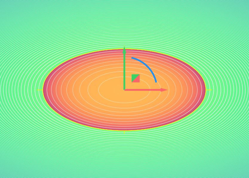
Before exporting your implicit file, use the nTop Field Viewer to check the health of your field. A healthy field will show contour lines that are parallel and equally spaced — this indicates the field is behaving as a proper Signed Distance Field (SDF) and will produce predictable results in slicing.
Enabling Show Defects and Highlight Zero
The Field Viewer has two toggles that are essential for pre-export validation:
- Show Defects — highlights discontinuities in the field as red zones. These are areas where the field value changes abruptly, which can cause artifacts in slicing, such as unexpected walls or holes in toolpaths.
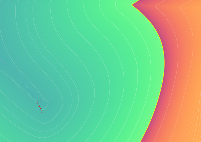
- Highlight Zero — identifies fake zeros, points where the field value is zero but should not be. Fake zeros can cause extra surfaces to appear when slicing inward.

Both toggles are found in the Field Viewer panel under the Tools tab. Enable both as a standard step before every export.
What to Look For
| What you see | What it means | Likely cause |
|---|---|---|
| Red zone on or near the surface | Field discontinuity | Boolean between coincident or touching surfaces |
| Unexpected zero surface away from the part boundary | Fake zero | Boolean where two bodies touch edge-to-edge |
| Contour lines that are uneven or non-parallel | Distorted field | Custom equations, remaps, or elliptical shapes |
If You See a Defect
Check the order of operations in your notebook. Work backward from the flagged implicit body to identify which operation is introducing the defect. The most common sources are:
- A Boolean where two bodies share a coincident face or touch edge-to-edge
- An imported mesh or CAD body that contains a defect carried into the implicit
Once the source is identified, the fix is typically adjusting the boolean so the tool body extends well beyond the target, eliminating the coincident condition. See the Modeling Best Practices section for guidance on structuring booleans correctly.
When to Check
Run a Field Viewer check after any boolean operation, not just at the end of the modeling process. Catching a defect close to where it was introduced makes it much easier to trace.
Common Field Quality Issues and What Causes Them
"Bad field" is a vague term. There are several distinct types of field quality issues, each with different causes and different effects on slicing output. Understanding which type you're dealing with makes it much easier to fix.
Field quality issues matter more when they occur in implicit bodies (the geometry itself) than in scalar fields (fields used to drive parameters like beam diameter or temperature distribution). The issues below are all relevant to implicit bodies.
False Zeros
What it is: The field value is zero at points that are clearly inside or outside the intended body, not on its boundary. These are false surface boundaries.
What causes it: Performing a boolean union on two bodies that touch externally, or a subtraction where two bodies touch internally (edge-to-edge or face-to-face coincident surfaces).
What you'll see in slicing: Extra walls appear, particularly when slicing inward. The slicer interprets the fake zero as a real surface boundary.
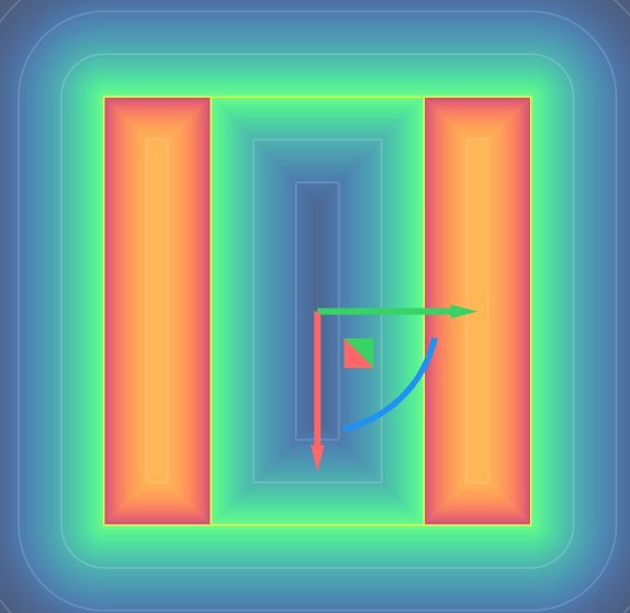
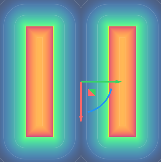
Classic example: Subtracting an inner cylinder from an outer cylinder to create a pipe, where both cylinders are the same length. The ends of the cylinders touch each other internally, creating false zeros along that boundary.
The fix is to make the inner cylinder longer than the outer — eliminating the coincident condition. Alternatively, revolve a rectangular profile to create the pipe shape entirely, thereby avoiding the Boolean operation altogether.
 |
 |
Discontinuities
What it is: The field value changes abruptly at certain points rather than transitioning smoothly. This shows up as a red zone in the Field Viewer when Show Defects is enabled.
What causes it: Boolean operations between touching bodies, imported mesh or CAD geometry that carries surface defects, or manually constructed fields using math or If-Else blocks. Beta blocks in your workflow can also cause this field discontinuity.
What you'll see in slicing: Rendering artifacts, unexpected holes, or irregular toolpaths near the affected region.
Note: Discontinuities far from the part's surface may not affect the slicing output. Discontinuities on or near the surface will.
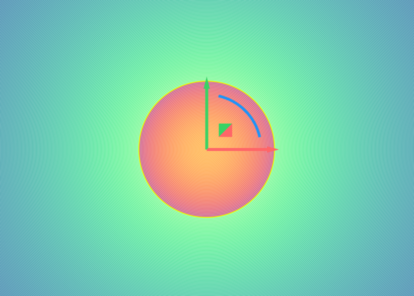
Distorted Fields (Non-Unit Gradient)
What it is: The field gradient magnitude is not equal to 1, meaning the field is not a proper Signed Distance Field. Contour lines in the Field Viewer will be uneven or non-parallel.
What causes it: Certain shapes — ellipses, ellipsoids, TPMS lattices — cannot be represented as true SDFs without additional processing. Custom implicit equations defined with math blocks can also produce this if not carefully constructed.
What you'll see in slicing: Wall thickness will not match what was specified. The actual thickness follows the field's contour lines, which may vary across the part.
 |
 |
Modeling Best Practices
These practices apply throughout the modeling process, not just at export time. Building these habits from the start will prevent most field-quality issues before they occur.
1. Avoid Coincident Surfaces During Booleans
Boolean operations are the most common source of field quality issues. The tool body should always extend well beyond the target body — never let two bodies share a face or touch edge-to-edge during a boolean.
- When subtracting, use a tool body that is larger than needed — ideally, much larger than the target
- Make complex shapes by extruding or revolving profiles instead of performing multiple booleans where possible
Example: To create a hollow pipe, do not subtract an inner cylinder that is the same length as the outer. Instead, use an inner cylinder that extends well beyond the outer, or revolve a rectangular profile to create the pipe shape in a single operation.
2. Trim and Intersect as Late as Possible
Keep bodies larger than necessary for as long as possible during the modeling process. Trimming and intersecting early introduces constraints that can cause unexpected behavior in downstream operations like offsetting and shelling.
Overbuild first, then trim at the end.
3. Build Fillets and Blends During Booleans, Not at the End
In implicit modeling, fillets and blends are applied at the time shapes are combined — not as a final step. Attempting to add fillets to arbitrary edges at the end of the process is unlikely to produce the result you want.
Plan blend radii as part of each boolean operation, not as a finishing pass.
4. Match Boolean Radius to Downstream Offset Distance
If you are performing a Boolean between two finite bodies and plan to offset or shell the result, the penetration distance between the two bodies should be at least as large as the offset distance you intend to use.
When booleaning into a thin wall, specifically, aim to overlap up to the center of the wall for the best results.
5. Avoid Beta Features for Production Workflows
Beta features are subject to change and may produce unexpected results. For files intended for Materialise slicing, use only stable, released functionality.
Pre-Export Checklist
Run through this before exporting any implicit file to Materialise.
Field Viewer
- Open the Field Viewer and enable Show Defects — confirm no red zones on or near the part surface. If they are far away from the surface, it will not cause any issues.
- Enable Highlight Zero — confirm no unexpected zero surfaces away from the part boundary
- Contour lines are parallel and equally spaced across the part
Booleans
- No boolean operations involve coincident or touching surfaces
- All tool bodies extend well beyond their target bodies
- Boolean's blend radius is at least as large as any intended offset or shell thickness
- Thin-wall booleans overlap up to the center of the wall
Modeling Process
- Blends were applied during Boolean operations, not added as a final step
- Trimming and intersecting are performed late in the process
- Avoid using beta features in the workflow
Imported Geometry
- Any imported mesh or CAD geometry was inspected in the Field Viewer by converting into Implicits before use in booleans