
Objective:
Learn how to apply lattices to only specific regions of a design.
Applies to:
- Latticing
Procedure:
There are several ways to accomplish this task, but the most straightforward is to use your CAD system to split the part into multiple regions before importing it to nTop. If you can isolate the region you want to lattice as its own CAD body, it will make the process easier and provide better control over your design.
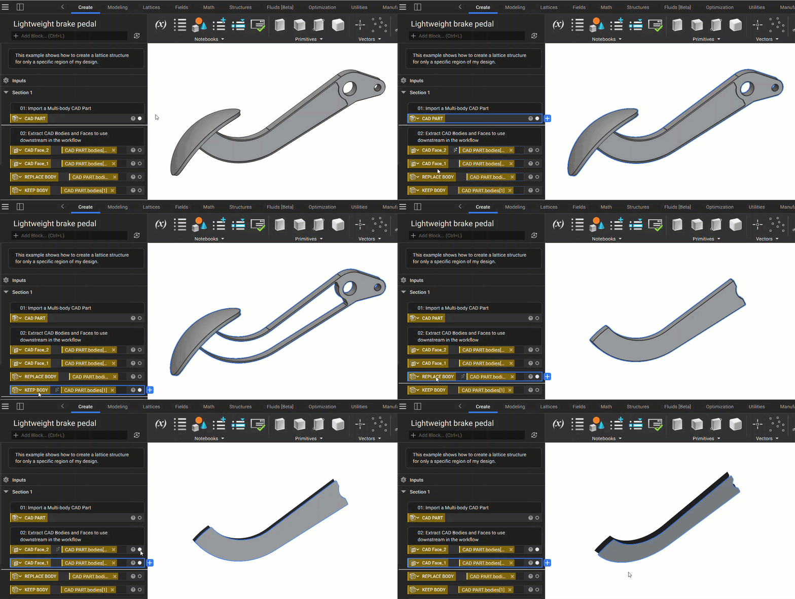
1. Import your multi-body CAD part and extract helpful variables. For this example, we're going to extract the following CAD features:
- The CAD Body of the area we want to lattice
- The CAD Body we want to keep
- The CAD Faces we are using to generate the lattice cell map.
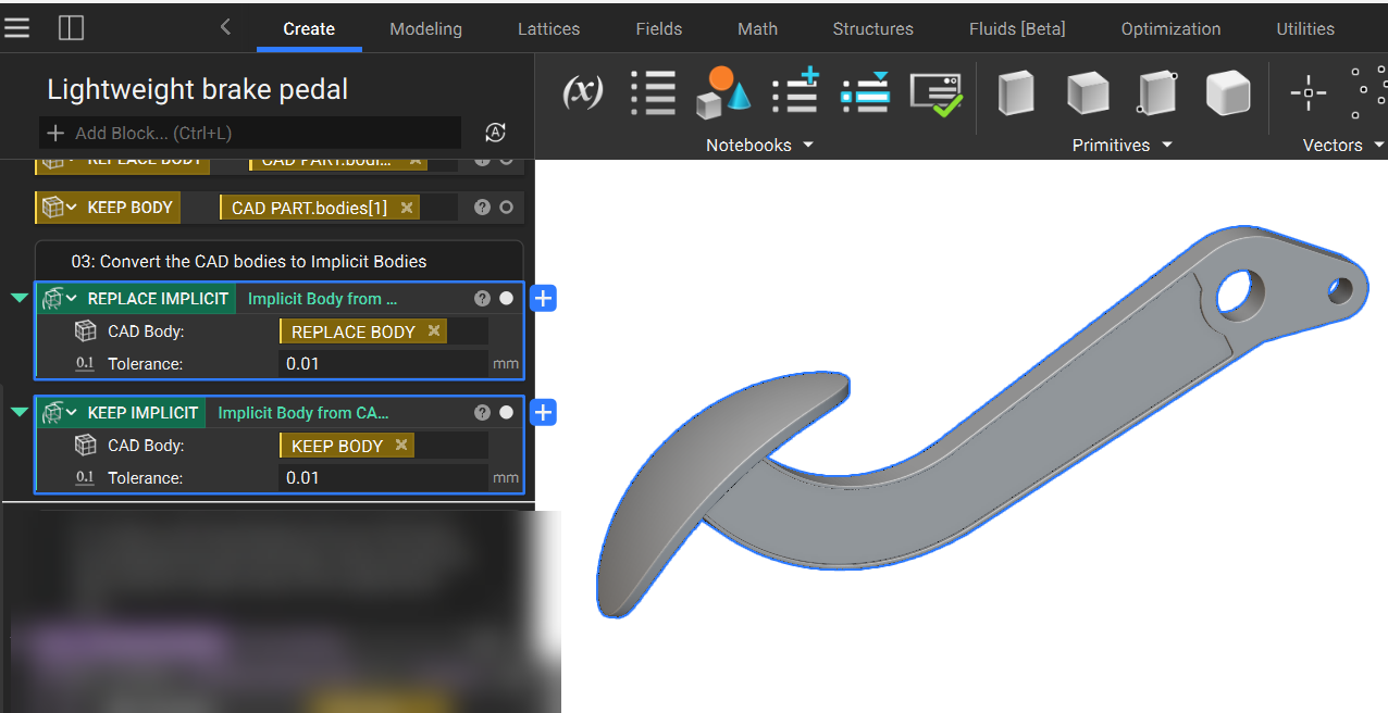
2. Convert the CAD bodies to implicit bodies. We will use these later downstream in the workflow.
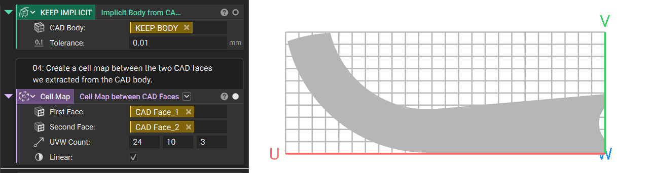
3. Create a cell map using the Cell Map Between CAD Faces block, and the two faces we extracted earlier.
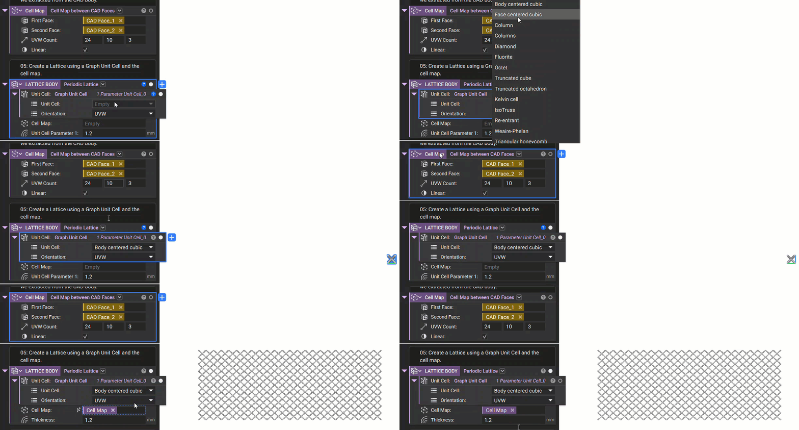
4. Use the new cell map and a Graph Unit Cell block to generate the Periodic Lattice.
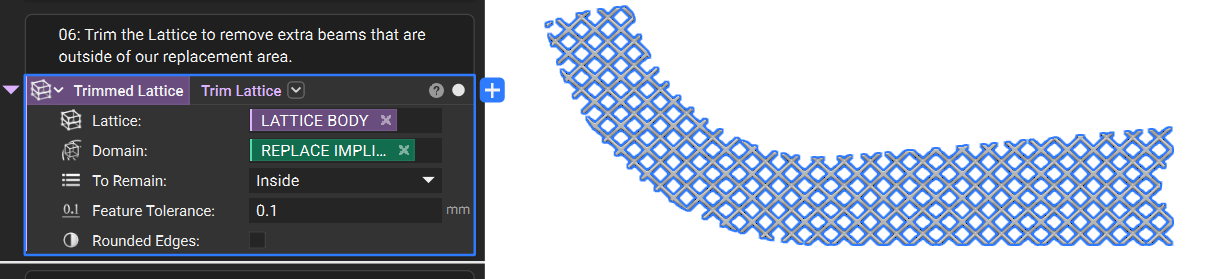
5. Using the Trim Lattice block, we can reduce the lattice structure to only remain within our REPLACE IMPLICIT region.
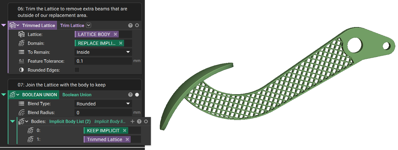
6. Finally we can use a Boolean Union block to merge the lattice with the original frame of the CAD body to create our finished part!
Are you still having issues? Contact the support team, and we’ll be happy to help!