Objective:
Learn how to use the Bounding Box 2D Nesting block (image below) to layout and Slice parts on a build plate.
Applies to:
- Additive Manufacturing
Procedure:
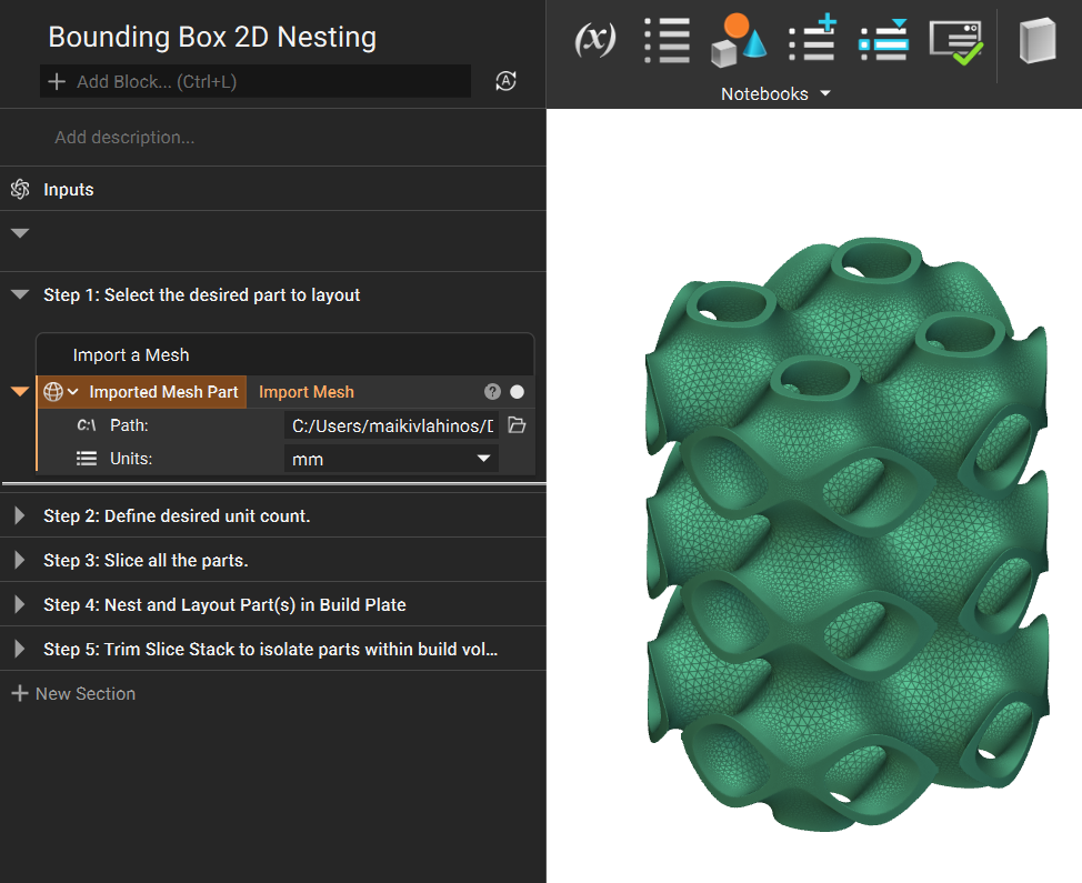
1. Select the part to layout
To nest objects in a bounding box, we can start with a Surface Mesh that has been imported into the notebook.
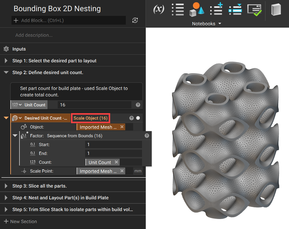
2. Define desired unit count
Use the Sequence from Bounds and Scale Object blocks to define the desired unit count.
- Add a Sequence from Bounds block
- Set the Start to 1
- Set the End to 1
- Set the Count to your desired count for the build plate.
- Add a Scale Object block
- Set the Object as your mesh
- Insert the Sequence from Bounds block into the Factor input
- Insert the Centroid from the Imported Mesh into the Scale Point input
The meshes are overlayed on one another and a List of Objects is created. As seen in the red box below, we have a List of 16 bodies. The List will be carried through for the rest of the workflow.
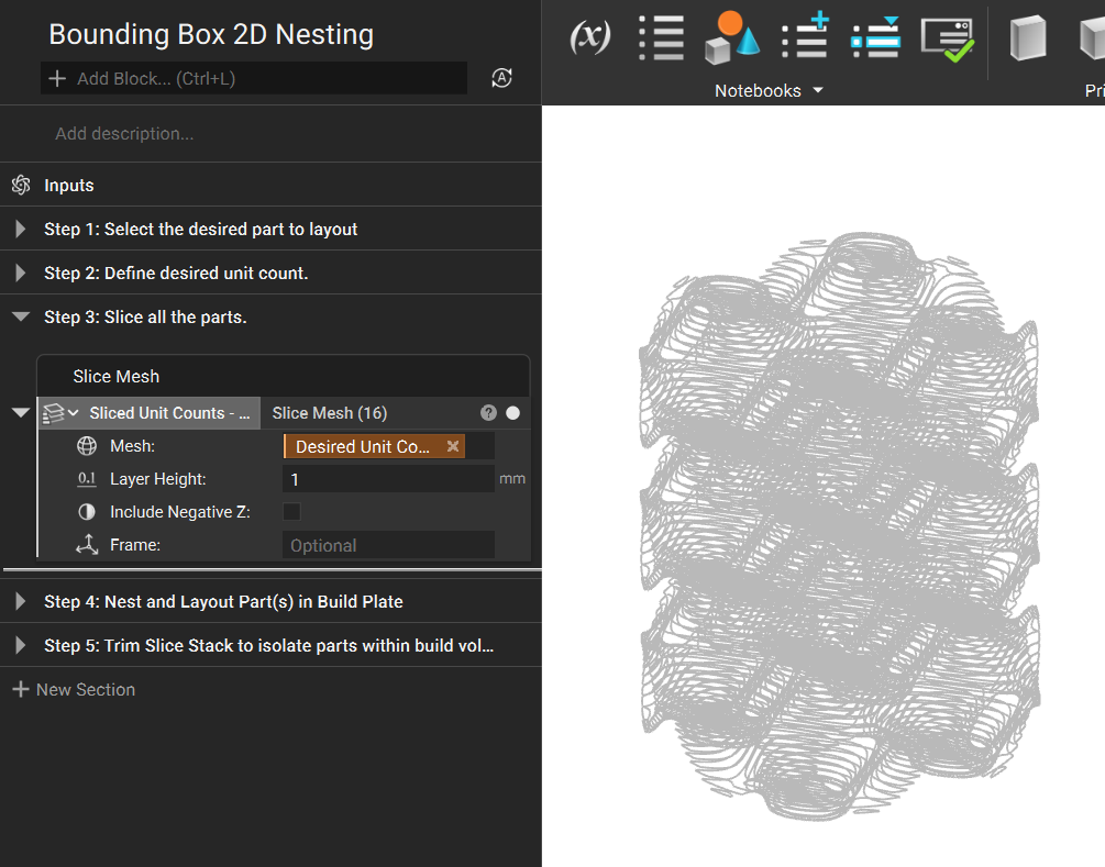
3. Slice the list of objects
- Add a Slice Mesh block
- Input the Scale Object block from Step 2.
- Set your layer height
Since we are using the Bounding Box 2D Nesting Block in the next step, we do not need to select Include negative Z or define a Frame.
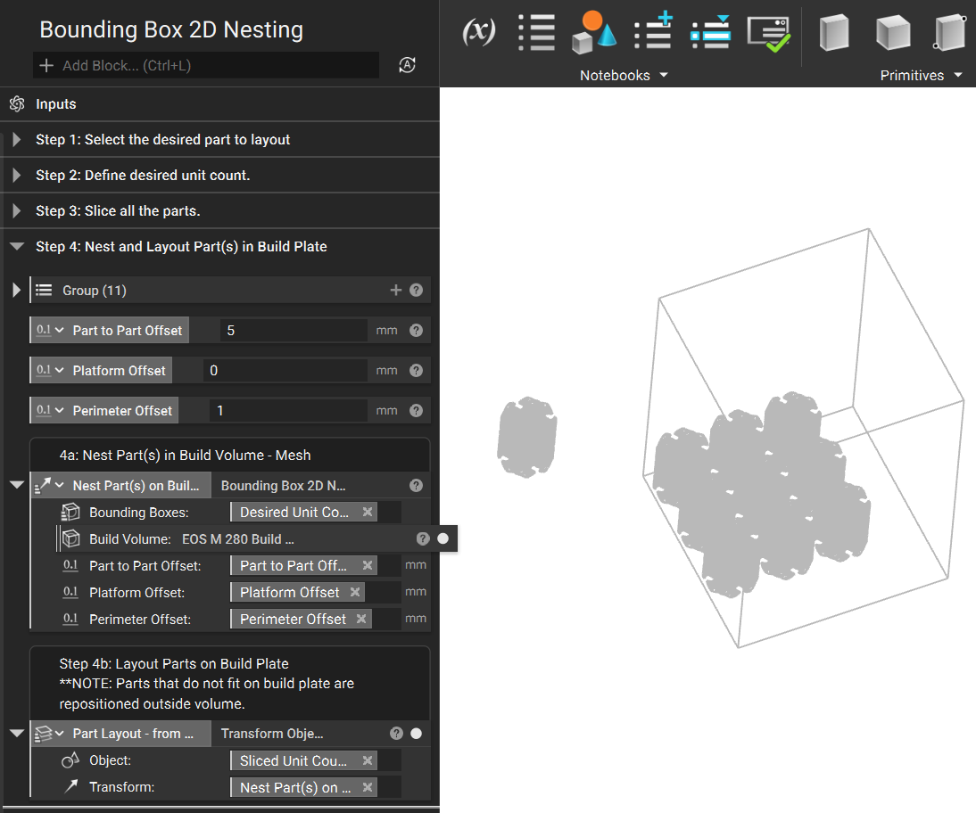
4. Nest and Layout Part(s) on Build Plate
4a. Nest Part(s) in Build Volume
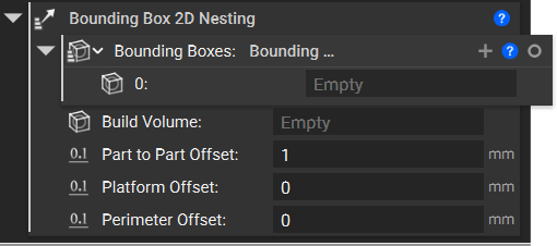
Add the Bounding Box 2D Nesting block and define the various nesting parameters; Build Volume, Part to Part Offset, Platform Offset, and Perimeter Offset.
The Bounding boxes input automatically includes an empty List. Delete this List and input the Slice Mesh list from the previous step.
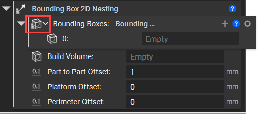
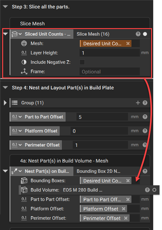
The additional Inputs for the Bounding Box 2D Nesting are Build Volume, Part to Part Offset, Platform Offset, and Perimeter Offset.
Build Volume:
You can choose between our current List of EOS/Renishaw/RenAM build volumes (found under the Additive Manufacturing tab) or define your own bounding box for a build volume.
Part to Part Offset, Platform Offset, and Perimeter Offset:
Have default values and define the spacing between the Parts as well as the offsets from the plate and exterior of the select Build Volume.
4b. Layout Part on Build Plate
- Add a Transform Object block
- Insert the Slice Mesh block from Step 3 for the Object input
-
Insert the Bounding Box 2D Nesting block from Step 4a into the Transform input
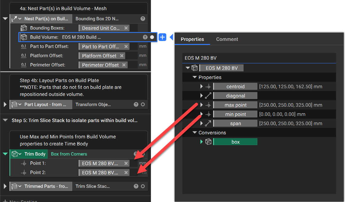
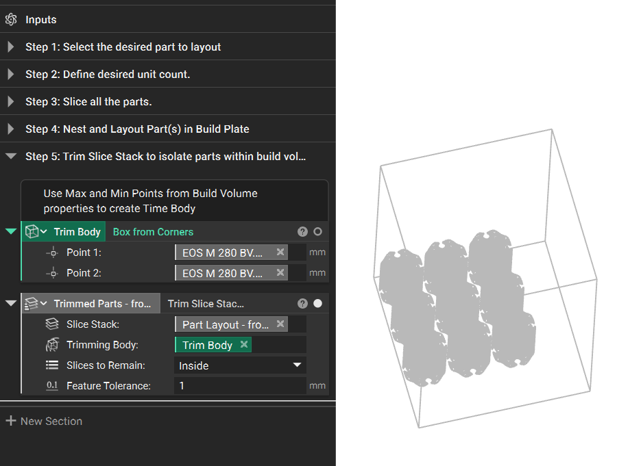
5. Trim slice stack to isolate parts within the build volume
- Add a Trim Slice Stack block
- Slice Stack: Insert the Transform Object block from Step 4b
- Trimming Body: Add a Box from Corners block
- Open up the Properties of the part in the Build Volume input (in the Bounding Box 2D Nesting block) and extract the Max Point and Min Point chips
- Insert the Property chips into the Box from Corners block
- Slices to Remain: Inside
- Feature Tolerance: as desired
The final output is a Sliced list of all the parts that fit on the Built Plate Volume and meet the desired constraints. In the example shown, 9 of the 16 bodies are able to fit on the build plate.
You have now completed the procedure for using the Bounding Box 2D Nest Block to arrange parts in preparation for an additive build.