Objective:
Learn how to use the Minimum Support Orientations block to determine an optimal orientation to minimize support.
If you would like a deeper look into the workflow or would like to follow along through the steps below, you can find the nTop file here: nTop File - How to use Minimum Support Orientations. The workflow shows how you can determine a series of transformations that optimally orient your part to minimize the supports needed for additive manufacturing.
Applies to:
- Additive manufacturing
Procedure:
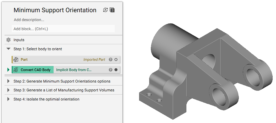
1. Select the body to orient
Import the part you want to orient.
2. Generate Minimum Support Orientation options
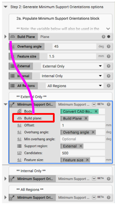
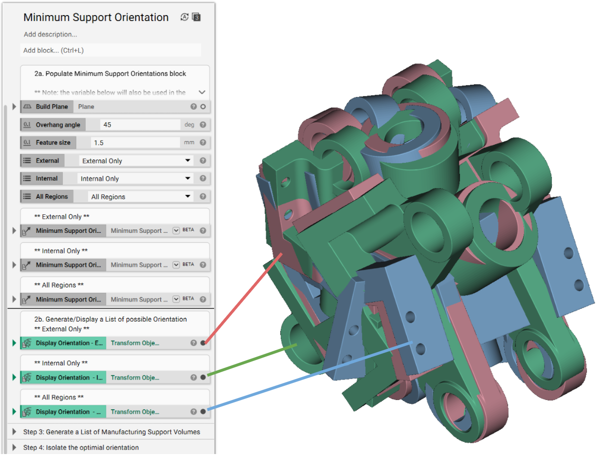
2a. Populate Minimum Support Orientation (MSO) block
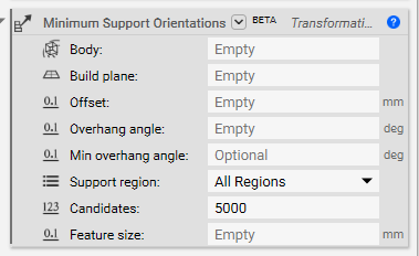
Create variables from the inputs: There are eight inputs to the MSO block. In this workflow, we extract four of them to make them variables (this is done by right-clicking on the Input in a block and selecting Make Variable - as seen in the image below) and bring them to the top level of the Notebook, making it easily accessible and transferable to other blocks.
Another block uses the Build Plane, Overhang angle, Support region, and Feature size. This workflow also examines all three Support region options: External Only, Internal Only, and All Regions.
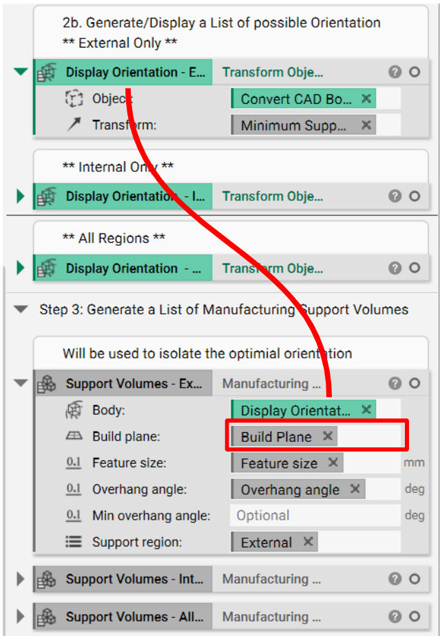
2b. Generate/Display a List of possible Orientation
The MSO block creates a Transformation List as an output, which needs to be displayed. This is done by using the Transform Object block.
- Add a Transform Object block
- Object: Implicit body we want to orient
- Transform: Minimum Support Orientation block
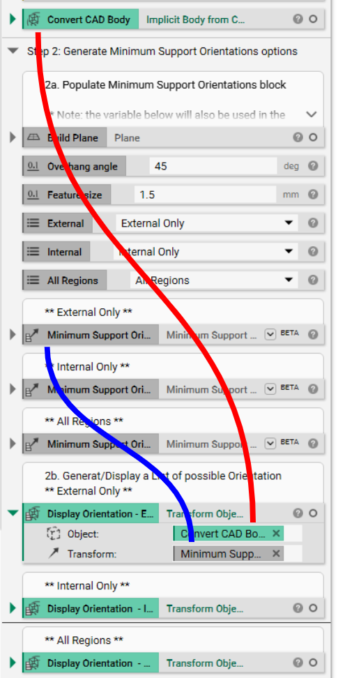
The Transform Object block now has a list of orientation options. As seen in the image below, there are a handful of possibilities for each Support region selection (External Only, Internal Only, and All Regions). As is, this list is not particularly useful. We need to isolate the desired orientation and the associated support region; the first step in this process is generating a List of support volumes.
3. Generate a List of Manufacturing Support Volumes
Use the Manufacturing Support Volume to generate a list of support volumes for each orientation option. The first input, Body, is the Transformed Object List we created in Step 2b (solid purple line below). The other inputs are the variables we extract in Step 2a.
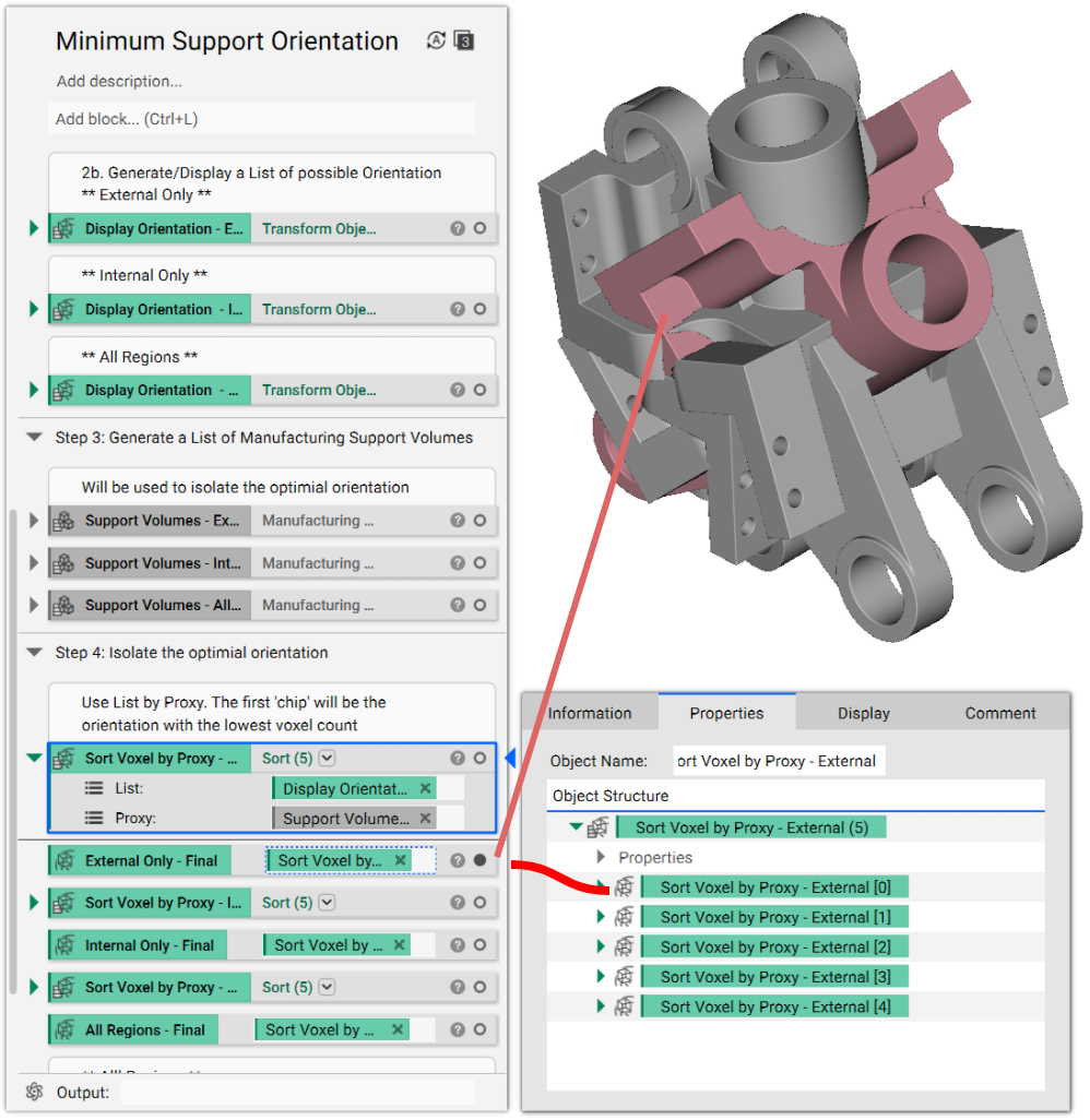
4. Isolate the optimal orientation
Several candidate orientations (typically 5) minimize the number of supports needed. We need to use the Transform Object List and the Manufacturing Support Volume List from above to isolate a single orientation that will minimize support. This method of isolating is called List by Proxy.
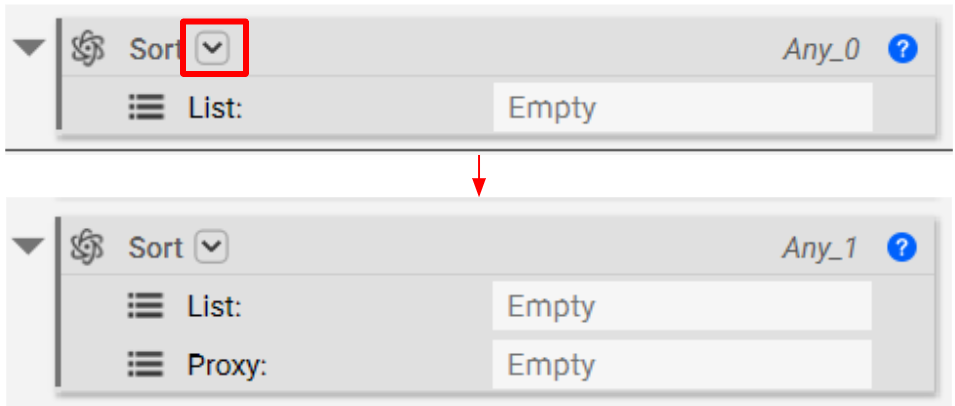
- Add a Sort block
- Click the down arrow (located in the encircled image below), and select "List Interface, List Interface" to add an additional input to the block called Proxy (seen below).
- List: Insert the Transformed Object List (from Step 2b)
- Proxy: Open the Properties of the Manufacturing Support Volume block. Navigate through the properties until you see the "Active Voxel Count" chip, and drag that chip into the input.
Tip: You can open the active voxel count chip further, as seen in the red box below. There we see a List of each support region generated and the number of voxels used to build that volume. Our Sort List by Proxy finds the smallest voxel count and associated orientation.
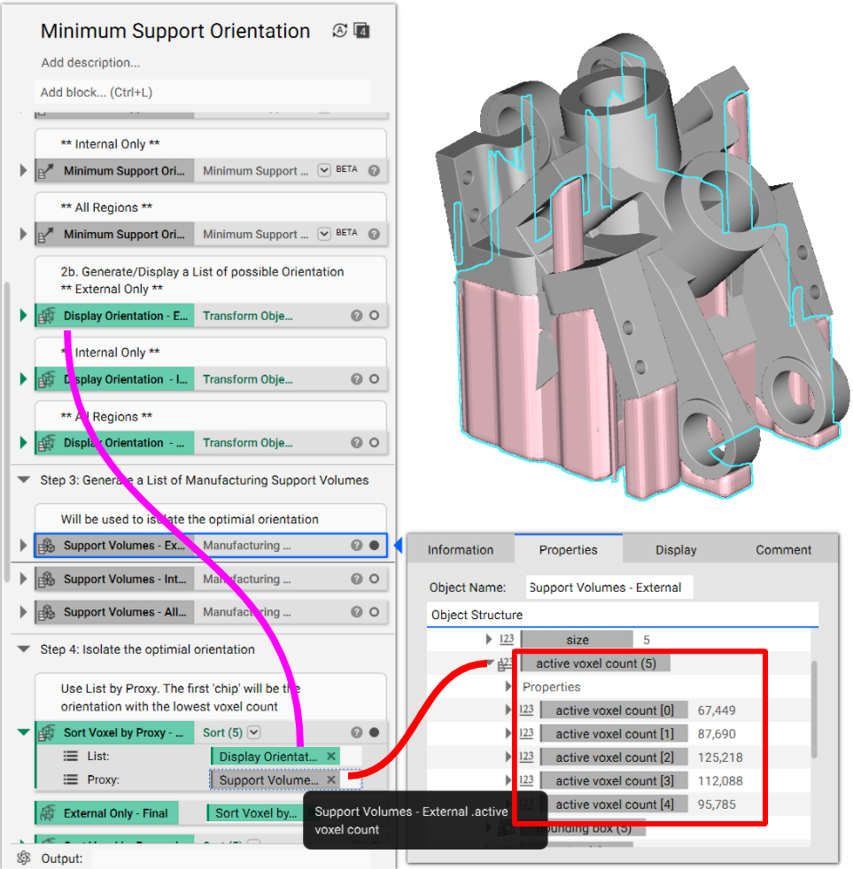
After the Sort block is satisfied, open the Properties, and the first chip in the List is the orientation that satisfies the minimum amount of supports (i.e. fewest voxels). Drag and drop that chip into the Notebook.
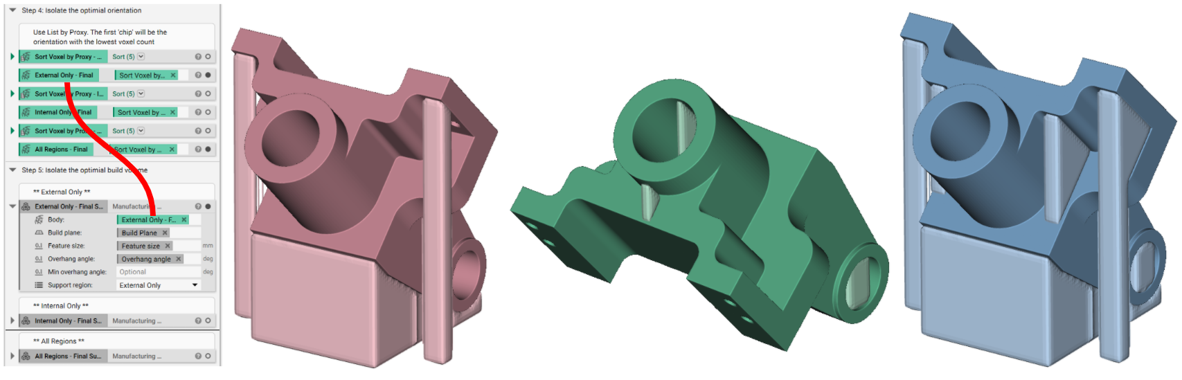
5. Isolate the optimal build volume
- Add a Manufacturing Support Volume block
- Set the inputs to the previously defined variables for Build Plane, Feature Size, and Overhang Angle
- Body: Insert the chip we extracted from the Sort block in Step 4 (solid red line below).
From here, we can infill the Support Volumes with any Lattice type (i.e. support structure).
And that’s it! You’ve successfully created a minimum support orientation for your part.
Are you still having issues? Contact the support team, and we’ll be happy to help!